


Web OS 10.0 Application Guide
252
Chapter 11: High Availability
212777-A, February 2002
Active-Standby Failover
The previous text described the use of a group of VRRP routers to form a single virtual inter-
face router. It implements a traditional hot-standby configuration in which the backup router
only functions when the active router has failed. VRRP can also be used to implement active-
standby configurations. In an active-standby configuration, both switches support active traf-
fic, but are configured so that they do not simultaneously support the same service.
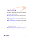
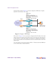
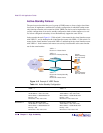
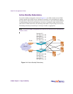
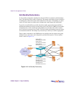
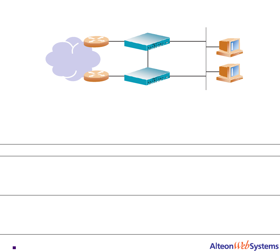
In the example shown in Figure 11-2, Web switch 1 is the master for the virtual interface router
with VRID = 1, and its backup for the virtual interface router with VRID = 2. Web switch 2 is
master for the virtual interface router with VRID = 2 and backup for the virtual interface router
with VRID = 1. In this manner, both routers can actively forward traffic at the same time but
not for the same interface.
Figure 11-2 Example 2: VRRP Router
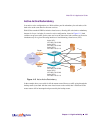
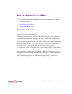
Table 11-1 Active Standby Configuration
VRID = 1 VRID = 2
Web Switch 1 Router #1 = Master Active
VR IP address = 205.178.13.226
MAC address = 00.00.SE.00.01.01
Priority = 255
IP interface = 205.178.13.226
Router #1 = Backup Standby
VR IP address = 205.178.13.240
MAC address = 00.00.SE.00.01.02
Priority = 100
IP interface = 205.178.13.239
Web Switch 2 Router #2 = Backup Standby
VR IP address = 205.178.13.226
MAC address = 00.00.SE.00.01.01
Priority = 100
IP interface = 205.178.13.225
Router #1 = Master Active
VR IP address = 205.178.13.240
MAC address = 00.00.SE.00.01.02
Priority = 255
IP interface = 205.178.13.240
Internet
Router
Router
VRID = 1
Router #2 = Backup Standby
VRID = 1
Router #1 = Master Active
Host #1
Default Gateway
205.178.13.226
Host #2
Default Gateway
205.178.13.240
Web Switch 1
Web Switch 2
VRID = 2
Router #2 = Master Active
VRID = 2
Router #1 = Backup Standby