


Web OS 10.0 Application Guide
46
Chapter 2: VLANs
212777-A, February 2002
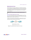
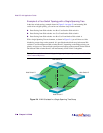
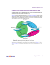
Example 1: Multiple VLANS with Tagging Adapters
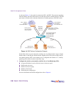
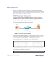
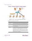
Figure 2-1 Example 1: Multiple VLANs with Tagging Gigabit Adapters
The features of this VLAN are described below:
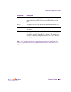
Component Description
Web Switch This switch is configured for three VLANs that represent three differ-
ent IP subnets. Two servers and five clients are attached to the switch.
Server #1 This server is part of VLAN 3 and only has presence in one IP subnet.
The port that the VLAN is attached to is configured only for VLAN 3,
so VLAN tagging is off.
Server #2 This high-use server needs to be accessed from all VLANs and IP sub-
nets. The server has an VLAN-tagging adapter installed with VLAN
tagging turned on. The adapter is attached to one of the Web switch’s
Gigabit Ethernet ports, that is configured for VLANs 1, 2, and 3. Tag-
ging is turned on. Because of the VLAN tagging capabilities of both the
adapter and the switch, the server is able to communicate on all three IP
subnets in this network. Broadcast separation between all three VLANs
and subnets, however, is maintained.
Server #1
VLAN #3
Server #2
Gigabit/Tagged
adapter
(All VLANs)
PC #1
VLAN #2
PC #2
VLAN #2
PC #3
VLAN #1
PC #4
VLAN #3
PC #5
Gigabit/Tagged
adapter
VLANs #1 & #2
Shared Media
Alteon
Web Switch