


Web OS 10.0 Application Guide
Chapter 11: High Availability
271
212777-A, February 2002
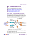
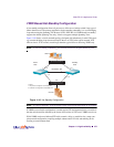
Task 3: Virtual Router Redundancy Configuration
1. Configure virtual routers 2, 4, 6, and 8.
These virtual routers will have the same IP addresses as the virtual server IP address. This is
what tells the switch that these are virtual service routers (VSRs). In this example, Layer 3
bindings are left in their default configuration, which is disabled.
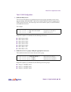
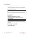
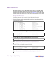
Configure a virtual router using the following sequence of commands:
Repeat this sequence of commands for the following virtual routers:
n VR 4 - VRID 4 - IF 5 (associate with IP interface #5)—Address 200.200.200.101
n VR 6 - VRID 6 - IF 5 (associate with IP interface #5)—Address 200.200.200.103
n VR 8 - VRID 8 - IF 5 (associate with IP interface #5)—Address 200.200.200.104
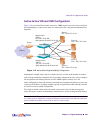
2. Configure virtual routers 1, 3, 5, and 7.
These virtual routers will act as the default gateways for the servers on each respective subnet.
Because these virtual routers are survivable next hop/default gateways, they are called virtual
interface routers (VIRs).
Configure each virtual router listed below, using the sequence of commands in Step 1.
n VR 1 - VRID 1 - IF 1 (associate with IP interface 1)—Address 10.10.10.1
n VR 3 - VRID 3 - IF 2 (associate with IP interface 2)—Address 20.10.10.1
n VR 5 - VRID 5 - IF 3 (associate with IP interface 3)—Address 30.10.10.1
n VR 7 - VRID 7 - IF 4 (associate with IP interface 4)—Address 40.10.10.1
>> Virtual server 4 # /cfg/vrrp/vr 2 (Select virtual router 2)
>> Virtual router 2 vrid 2 (Set virtual router ID)
>> Virtual router 2 addr 200.200.200.100 (Assign virtual router IP address)
>> Virtual router 2 if 5 (Assign virtual router interface)
>> Virtual router 2 ena (Enable virtual router 2)