


Web OS 10.0 Application Guide
Chapter 3: Port Trunking
67
212777-A, February 2002
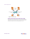
Port Trunking Example
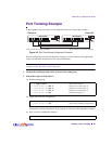
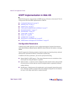
In the example below, three ports will be trunked between two Alteon Web switches.
Figure 3-2 Port Trunk Group Configuration Example
Prior to configuring each switch in the above example, you must connect to the appropriate
switch’s Command Line Interface (CLI) as the administrator.
NOTE – For details about accessing and using any of the menu commands described in this
example, see the Web OS Command Reference.
1. Connect the switch ports that will be involved in the trunk group.
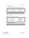
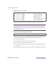
2. Follow these steps on Web switch 1:
(a) Define a trunk group.
(b) Apply and verify the configuration.
Examine the resulting information. If any settings are incorrect, make appropriate changes.
(c) Save your new configuration changes.
>> # /cfg/trunk 1 (Select trunk group 1)
>> Trunk group 1# add 2 (Add port 2 to trunk group 1)
>> Trunk group 1# add 4 (Add port 4 to trunk group 1)
>> Trunk group 1# add 5 (Add port 5 to trunk group 1)
>> Trunk group 1# ena (Enable trunk group 1)
>> Trunk group 1# apply (Make your changes active)
>> Trunk group 1# cur (View current trunking configuration)
>> Trunk group 1# save (Save for restore after reboot)
Link
Data
Active
Link
Data
Active
9
8
TX RX
TX
RX
Power Console
5
TX RX
4
TX RX
3
TX RX
1
TX RX
2
TX RX
6
TX RX
Web Switch
10/100/10000 Mbps Ethernet Server Switch
7
TX RX
Link
Data
1000
Base-SX
Gigabit
Powered
Link
Data
Active
Link
Data
Active
9
8
TX RX
TX
RX
Power Console
5
TX RX
4
TX RX
3
TX RX
1
TX RX
2
TX RX
6
TX RX
Web Switch
10/100/10000 Mbps Ethernet Server Switch
7
TX RX
Link
Data
1000
Base-SX
Gigabit
Powered
Trunk 1: Ports 2, 4, and 5 on Switch 1 Trunk 3: Ports 4, 6, and 9 on Switch 2
042
2 4 5
4 6
9
Switch #2Switch #1