


Web OS 10.0 Application Guide
Chapter 2: VLANs
53
212777-A, February 2002
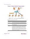
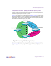
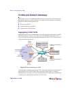
Example of a Four-Switch Topology with Multiple Spanning Trees
If multiple Spanning Trees are implemented and each VLAN is on a different Spanning Tree,
elimination of logical loops will not isolate any VLAN.
Figure 2-5 shows the same four-switch topology as in Figure 2-4 on page 52, but with multiple
Spanning Trees enabled. The VLANs are identified on each of the three shaded areas connect-
ing the switches. The port numbers are shown next to each switch. The Spanning Tree Group
(STG) number for each VLAN is shown at the switch.
Figure 2-5 Implementing Multiple Spanning Tree Groups
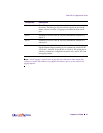
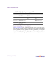
Three instances of Spanning Tree are configured in the example shown in Figure 2-5. Refer to
Table 2-2 on page 54 to identify the Spanning Tree group a VLAN is participating in for each
switch.
STG 1
STG 1
VLAN 1
Web Switch B
Web Switch C
Web Switch D
Web Switch A
VLAN 2
VLAN 3
Port 1
Port 1
Port 1
Port 2
Port 2
Port 8
STG 2
Port 8
Port 1
STG 1
Port 8
STG 2
Port 8
STG 2
STG 1