


Web OS 10.0 Application Guide
38
Chapter 1: Basic IP Routing
212777-A, February 2002
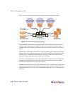
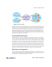
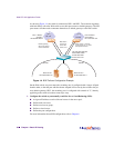
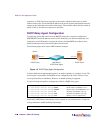
As shown in Figure 1-4, the switch is connected to ISP 1 and ISP 2. The customer negotiates
with both ISPs to allow the Web switch to use their peer routers as default gateways. The ISP
peer routers will then need to announce themselves as default gateways to the Web switch.
Figure 1-4 BGP Failover Configuration Example
On the Web switch, one peer router (the secondary one) is configured with a longer AS path
than the other, so that the peer with the shorter AS path will be seen by the switch as the pri-
mary default gateway. ISP 2, the secondary peer, is configured with a metric of “3,” thereby
appearing to the switch to be three router hops away.
1. Configure the switch as you normally would for Server Load Balancing (SLB).
n Assign an IP address to each of the real servers in the server pool.
n Define each real server.
n Define a real server group.
n Define a virtual server.
n Define the port configuration.
For more information about SLB configuration, refer to Chapter 6.
ISP 2
Default gateway,
with routes having
shorter AS PATH
VIP: 200.200.200.200
Alteon Web switch
IP: 200.200.200.1
IP:210.210.210.1
Web switch
announces
routes with
metric of "3"
Peer 1 Router
(Primary)
IP: 200.200.200.2
AS 100
ISP 1
AS 200
Real server 2
IP: 200.200.200.11
Real server 1
IP: 200.200.200.10
AS 300
AS 300
Peer 2 Router
(Secondary)
IP: 210.210.210.2
Alteon metric = AS path
length (metric of '3' = local
AS repeated 3 times