


Web OS 10.0 Application Guide
126
Chapter 6: Server Load Balancing
212777-A, February 2002
5. Define a virtual server.
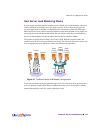
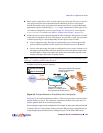
All client requests will be addressed to a virtual server IP address on a virtual server defined on
the switch. Clients acquire the virtual server IP address through normal DNS resolution. In this
example, HTTP is configured as the only service running on this virtual server, and this service
is associated with the real server group. For example:
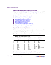
NOTE – This configuration is not limited to HTTP Web service. Other TCP/IP services can be
configured in a similar fashion. For a list of other well-known services and ports, see “Well-
Known Application Ports” on page 128. To configure multiple services, see “Configuring Mul-
tiple Services” on page 130.
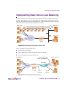
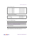
6. Define the port settings.
In this example, the following ports are being used on the Web switch:
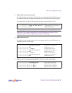
>> Real server group 1# /cfg/slb/virt 1 (Select virtual server 1)
>> Virtual server 1# vip 200.200.200.1 (Assign a virtual server IP address)
>> Virtual server 1# ena (Enable the virtual server)
>> Virtual server 1# service http (Select the HTTP service menu)
>> Virtual server 1 http Service# group 1 (Associate virtual port to real group)
Table 6-2 Web Host Example: Port Usage
Port Host L4 Processing
1 Server A serves SLB requests. Server
2 Server B serves SLB requests. Server
3 Server C serves SLB requests. Server
4 Back-end NFS server provides centralized Web content for all three
real servers. This port does not require Web switching features.
None
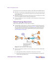
5 Client router A connects the switch to the Internet where client
requests originate.
Client
6 Client router B connects the switch to the Internet where client
requests originate.
Client