


Web OS 10.0 Application Guide
Chapter 13: Firewall Load Balancing
327
212777-A, February 2002
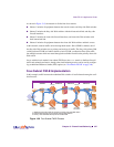
As shown in Figure 13-5, the network is divided into four sections:
n Subnet 1 includes all equipment between the exterior routers and dirty-side Web switches.
n Subnet 2 includes the dirty-side Web switches with their interswitch link, and dirty-side
firewall interfaces.
n Subnet 3 includes the clean-side firewall interfaces, and clean-side Web switches with
their interswitch link.
n Subnet 4 includes all equipment between the clean-side Web switches and their servers.
In this network, external traffic arrives through both routers. Since VRRP is enabled, one of
the dirty-side Web switches acts as primary and receives all traffic. The dirty-side primary Web
switch performs FWLB in a fashion similar to basic FWLB: a redirection filter splits traffic
into multiple streams which are routed through the available firewalls to the primary clean-side
Web switch.
Just as with the basic method, four-subnet FWLB uses the hash metric to distribute firewall
traffic and maintain persistence, though other load-balancing metrics can be used by configur-
ing an additional Return to Sender (RTS) option (see “Free-Metric FWLB” on page 346).
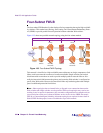
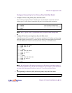
Four-Subnet FWLB Implementation
In this example, traffic between the redundant Web switches is load balanced among the avail-
able firewalls.
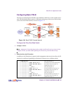
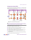
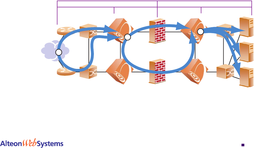
Figure 13-6 Four-Subnet FWLB Process
Subnet 1 Subnet 2 Subnet 3 Subnet 4
Dirty Side Clean Side
Internet
Routers
Simple
Switches
Simple
Switches
Firewalls Secondary
Web Switch
Primary Primary
Secondary
Web Switch
Servers
1
2
3
1. VRRP forces incoming traffic to converge on primary dirty-side Web switch
2. Firewall load balancing occurs between primary Web switches
3. Primary clean-side Web switch performs standard SLB