


Web OS 10.0 Application Guide
Chapter 11: High Availability
267
212777-A, February 2002
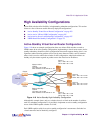
Active/Active Server Load Balancing Configuration
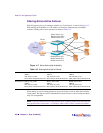
In this example, you set up four virtual servers each load balancing two servers providing one
service (for example, HTTP) per virtual server.
You are load balancing HTTP, HTTPS, POP3, SMTP, and FTP. Each protocol is load balanced
via a different virtual server. You could load balance all of these services on one VIP, but in this
example, four distinct virtual servers are used to illustrate the benefits of active/active failover.
Set up one switch, dump out the configuration script (also called a text dump), edit it, and
dump the edited configuration into the peer switch.
NOTE – Configuring the switch for active-active failover should take no longer than 15 min-
utes to complete. You can use either the Web OS Browser-Based Interface (BBI) or the Com-
mand Line Interface (CLI) for configuration.
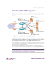
Task 1: Background Configuration
1. Define the IP interfaces.
The switch will need an IP interface for each subnet to which it will be connected so it can
communicate with devices attached to it. Each interface will need to be placed in the appropri-
ate VLAN. In our example, Interfaces 1, 2, 3, and 4 will be in VLAN 2 and Interface 5 will be
in VLAN 1.
NOTE – On Alteon Web switches, you may configure more than one subnet per VLAN.
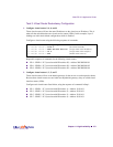
To configure the IP interfaces for this example, enter the following commands from the CLI:
Repeat the commands for each interface listed below:
n IF 2 20.10.10.10
n IF 3 30.10.10.10
n IF 4 40.10.10.10
n IF 5 200.1.1.10
>> Main# /cfg/ip/if 1 (Select IP interface 1)
>> IP Interface 1 # addr 10.10.10.10 (Assign IP address for the interface)
>> IP Interface 1 # vlan 2 (Assign VLAN for the interface)
>> IP Interface 1 # ena (Enable IP interface 1)