


Web OS 10.0 Application Guide
264
Chapter 11: High Availability
212777-A, February 2002
To implement the active-standby example, perform the following switch configuration:
1. Configure the appropriate Layer 2 and Layer 3 parameters on both switches.
This includes any required VLANs, IP interfaces, default gateways, and so on. If IP interfaces
are configured, none should use the virtual server IP address described in Step 4.
2. Define all filters required for your network configuration.
Filters may be configured on one switch and synchronized with settings on the other switch
(see Step 5 below).
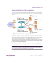
3. Configure all required SLB parameters on Web switch 1.
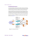
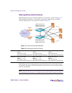
For the purposes of this example, assume that Web switch 1 in Figure 11-8 is configured in this
step. Required Layer 4 parameters include a VIP = 205.178.13.226 and one real server group
with four real servers, RIP = 205.178.13.101, RIP = 205.178.13.102, RIP = 205.178.13.103,
and RIP = 205.178.13.104.
4. Configure the VRRP parameters on Web switch 1.
This configuration includes VRID = 2, VIP = 205.178.13.226 and the priority. Enable tracking
and set the parameters appropriately (refer to “Configuring the Switch for Tracking” on page
280). Make sure to disable sharing.
5. Synchronize the SLB and VRRP configurations by synchronizing the configuration from
Web switch 1 to Web switch 2.
Use the /oper/slb/synch command (see “Synchronizing Configurations” on page 282).
6. Change the real servers in the Web switch 2 configuration to RIP = 205.178.13.105,
RIP = 205.178.13.106, RIP =205.178.13.107, and RIP = 205.178.13.108.
Adjust Web switch 2’s priority (see “Configuring the Switch for Tracking” on page 280).
In this example, with Web switch 1 as the master, if a link between Web switch 1 and a server
fails, the server will fail health checks and be taken out of the load-balancing algorithm. If track-
ing is enabled and is configured to take into account the number of healthy real servers for the
Virtual Router's VIP address, Web switch 1’s priority will be reduced. If it is reduced to a value
lower than Web switch 2’s priority, then Web switch 2 will assume the role of master. In this
case, all active connections serviced by Web switch 1’s virtual server IP address are severed.
If the link between Web switch 1 and its Internet router fails, the protocol used to distribute
traffic between the routers, for example, Open Shortest Path First (OSPF), will reroute traffic
to the other router. Web switch 2 (backup) will act as a Layer 2/3 switch and forward all traffic
destined to the virtual server IP address to Web switch 1.
If the entire Web switch 1 (master) fails, the protocol used to distribute traffic between the
routers, such as OSPF, will reroute traffic to Web switch 2. Web switch 2 (backup) detects that
the master has failed because it will stop receiving advertisements. The backup then assumes
the master's responsibility of responding to ARP requests and issuing advertisements.