


26 MSC8101ADS RevB User’s Manual MOTOROLA
Operating Instructions
4 - Operating Instructions
4•1 INTRODUCTION
This chapter provides necessary information to use the MSC8101-ADS in host-controlled and
stand-alone configurations. This includes controls and indicators, memory map details, and
software initialization of the board.
4•2 SWITCHES
The MSC8101ADS has the following switches:
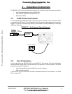
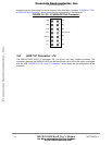
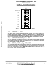
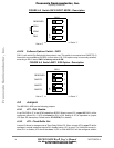
4•2•1 Host I/F Setting - SW1
This switch is using for manually set a Host Bus parameters. When Host Configuration is enable
the DIP switch SW1/1-3 will be connected to Data Bus through tri-state buffers and sampled by the
Processor. The SW1 factory set is all ON.
FIGURE 4-1 Switch SW1 HOST - Description
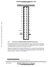
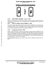
4•2•2 Emulator Enable (EE) - SW2
This switch controls lines EE0-EE7,EED, connected to appropriate pins of the Processor. When
Reset Configuration executed, EEs lines, involved in one, are driven by FPGA. In fact, they are
EE0, EE1, EE4 and EE5 which sampled at the rising edge of PORESET~. After configuration is
done level of all EE-signals is set by the switch SW2/1-7. Their status may be read out via
BCSR3/0-6. SW2 is factory set to all ON.
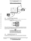
SW1
ON
1
2
3
4
StrobePolarity
DualSingleStrobe
8/16BIT
RESERVED
Set to ‘0’
<=
=> Set to ’1’
Frees
cale Semiconductor,
I
Freescale Semiconductor, Inc.
For More Information On This Product,
Go to: www.freescale.com
nc...