


40 MSC8101ADS RevB User’s Manual MOTOROLA
Functional Description
Hard-Reset configuration word. This configuration may be taken from an internal default, in case
RSTCONF
is negated during HRESET asserted or taken from the Flash memory (MS 8 bits of the
data bus) or Altera device
A
in case RSTCONF signal is asserted along with HRESET. Its meant
Hardware Reset Configuration in different of Host Reset Configuration that available while HPE-
Host Port Enable input of the MSC8101 is sampled high at the rising edge of PORESET
the Host
Port is enabled and a Configuration Word is got from Host I/F. The default configuration word can
be taken from the Flash or from the Altera device in case the Flash has been tampered with. The
selection between the Flash and the Altera device as the source of the default configuration word
is determined by a dedicated jumper.
During hard reset sequence while Host Port Disable (HPE is low) the configuration master reads
the Flash (or Altera device) memory at addresses 0, 8, 0x18, 0x20,... a byte each time, to assemble
the 32 bit configuration word. If the HPE pin and RSTCONF
are sampled high the Host Port is
enable by Slave Configuration Reset mode. The Host device which must not be MSC8101 write
two 16-bit words to program 32-bit Reset Conf. Word. See a table below including the several boot
mode.
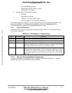
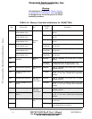
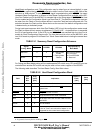
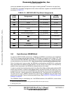
TABLE 5-1 Summary Reset Configuration Schemes.
For Debug and Boot Mode setting will be used separate DIP switch array. EEs and EED pins are
controlled from another DIP switch and may be read out from status register of the BCSR3.
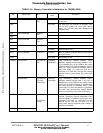
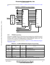
The following table describes The Hard Reset Config. Word field values:
A. In general, from any device residing on CS0.
Signal/
Config. Mode
RSTCONF
HPE/EE1 EE0/DBG
EE[4-5]/BTM[1-0]
Boot Mode
MASTER 0 0 0 - Debug Mode
Enable
1- Debug Mode
Disable
00-From ext. memory
01-From HOST
10-From EEPROM
11- Reserved
HOST 1 1
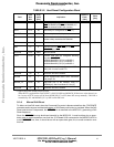
TABLE 5-2. Hard Reset Configuration Word
Field
Data
Bus
Bits
Prog
Value
[Bin]
Implication
Offset In
Flash
[Hex]
Value
[Hex]
EARB 0 ’0’ Internal Arbitration Selected. 0 2C
EXMC 1 ’0’ Internal Memory Controller. CS0
active at
system boot.
IRQ7INT
2’1’INT_OUT function is active
EBM 3 ’0’ Single Quartz001 bus mode is assumed
BPS 4:5 ’11’ 32 Bit Boot Port Size for both Flash memory
and BCSR
SCDIS 6 ’0’ SC140 enabled
ISPS 7 ‘0’ Internal space port size for ext. master access
is 64 bit. Don’t care since this feature is not
supported for the current board configuration.
Frees
cale Semiconductor,
I
Freescale Semiconductor, Inc.
For More Information On This Product,
Go to: www.freescale.com
nc...