


34 MSC8101ADS RevB User’s Manual MOTOROLA
Operating Instructions
Note
Application S/W should always seek to match
the state of LD13 to the status of the LXT970, so
that, this indication is made reliable as to the
correct status of the LXT970.
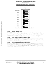
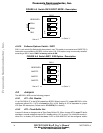
4•4•14 ATM ON - LD14
When the yellow ATM ON LED is lit, it indicates that the ATM-UNI transceiver - the PM5350, is
active and enables communication via that medium. When it is dark, the ATM-UNI transceiver is
disconnected from the MSC8101, enabling the use of its associated FCC1 pins off-board via the
expansion connectors.
ATM ON LED is controlled by BCSR1/2.
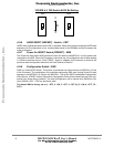
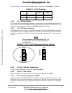
4•4•15 T1-1 TDM Port 1 Enable - LD15
When the yellow T1-1 LED is lit, it indicates that T1/E1 QFALC port 1 is connected to the CPM
TDMA1 port. When darkened, it designates that associated CPM TDMA1 lines may be used for
the CODEC application, in case when CODEC LED is lit. The LD15 reflects the bit BCSR0/3
T1_1EN.
4•4•16 T1-234 TDM Ports 2,3,4 Enable - LD16
When the yellow T1-234 LED is lit, it indicates that T1/E1 QFALC ports 2-4 are available. When
darkened, it designates that associated CPM’s TDMB2,TDMC2,TDMD2 lines may be used for the
other application, e.g. Fast Ethernet. The LD16 reflects the bit BCSR0/4 T1_234EN.
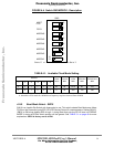
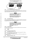
4•4•17 CODEC Enable - LD17
When the yellow CODEC LED is lit, it indicates that CODEC lines are connected to the CPM
TDMA1 port instead of T1/E1 QFALC port 1. When darkened, the CODEC device is isolated from
the bus by tri-state buffers. The LD17 reflects the bit BCSR1/1 CODEC_EN.
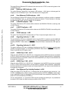
4•4•18 RUN Indicator - LD18
When the green RUN LED - LD18 is lit, it indicates that the MSC8101 is performing cycles on the
PPC Bus. When dark, the Processor is either running internally or stuck.
4•4•19 Host I/F Enable - LD19
When the yellow Host I/F ON LED is lit, it indicates that the Processor implementes HDI16 port.
It’s is available on the Host connector P4 and expansion connectors P1, P2. When darkened, PPC
Data Bus becomes 64-bit width with no Host I/F support.
4•4•20 1.5V Indicator - LD20
The green 1.5V LED - LD20, indicates the presence of the +1.5V supply with output voltage no
less than 0.9V.
4•4•21 3.3V Indicator - LD21
The green 3.3V LED - LD21, indicates the presence of the +3.3V supply on the ADS.
4•4•22 5V Indicator - LD22
The green 5V LED - LD22, indicates the presence of the +5V external supply on the ADS.
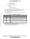
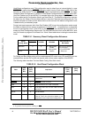
4•5 The MSC8101’s Registers’ Programming
The MSC8101 provides the following functions on the MSC8101ADS:
1) System functions which include:
Frees
cale Semiconductor,
I
Freescale Semiconductor, Inc.
For More Information On This Product,
Go to: www.freescale.com
nc...