


B-76 MSC8101ADS RevB User’s Manual MOTOROLA
10
10
In this chapter all information needed for support, maintenance and connectivity to the
MSC8101ADS is provided.
B•1 Interconnect Signals
The MSC8101ADS interconnects with external devices via the following set of connectors:
1) P1 - System Expansion
2) P2 - CPM Expansion
3) P3 - Altera’s In System Programming (ISP)
4) P4 - Host I/F
5) P5, P7, P8, P9, P10, P13, P14 - Logic Analyzer MICTOR Connectors
6) P6 - JTAG/ONCE
7) P12 - 100 / 10 - Base-T Ethernet port
8) P15,P16 - SMB Coax Connectors
9) P17,P18 - Double RJ45 for T1/E1 port
10) P19,P21,P24 - Stereo Phone Jack
11) P20,P22,P23,P25 - RCA Jack
12) P26 - 5V Power Supply
13) P27A,B - RS232 port 1,2
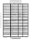
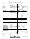
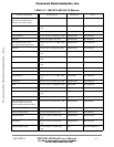
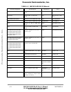
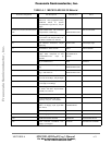
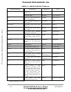
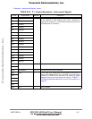
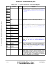
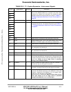
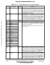
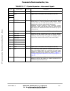
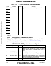
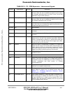
B•1•1 MSC8101ADS’s P1- System Expansion Connector
P1 is a 128 pin, 90
0
, DIN 41612 connector, which provide a minimal system I/F required to inter-
face various types of communication transceivers, data path of which passes through MSC8101’s.
This connector contains 16 bit (lower PPC bus) address lines, 16 bit (higher PPC bus) Data lines
plus useful GPCM and UPM control lines. The pinout of P1 is shown in TABLE B1-2. "P1 - System
Frees
cale Semiconductor,
I
Freescale Semiconductor, Inc.
For More Information On This Product,
Go to: www.freescale.com
nc...