


54 MSC8101ADS RevB User’s Manual MOTOROLA
Functional Description
pansion Connector is using for off-board tools (ECOM,DMA e.g.) it’s necessary to avoid signal col-
lisions. For this purpose Host I/F buffers should be disabled for external non-dedicated tools. The
placement Host I/F signals is shown in the following table.
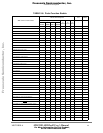
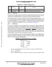
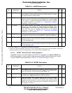
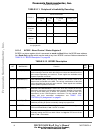
TABLE 5-8. Host I/F Interconnect signals
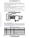
5•10 DMA off-board tool
The MSC8101 has multi-channel DMA connected to both PPC and Internal Local Bus. The DMA
supports flyby transfer between peripheral and memory when they have the same port size. For
testing flyby mode will be used off-board tool consists FIFO’s array and control logic placing on the
wire-wrap prototype board. This tool allows to check DRACK (DMA Request Logic) and DONE
logic. The tool will be connected to CPM Expansion Connectors.
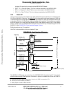
5•11 Board Control & Status Register - BCSR
Most of the hardware options on the ADS are controlled or monitored by the BCSR, which is a 32
bit wide read / write register file. BCSR resides over the PPC Bus, accessed via the MSC8101’s
memory controller (see TABLE 5-3. "MSC8101ADS Chip Select Assignments" on page 44) and in
fact includes 8 registers: BCSR0 to BCSR7. Since the minimum block size for a CS region is
32KBytes and only A(27:29) lines are decoded by the BCSR for register selection, BCSR0 -
BCSR7 are duplicated many times inside that region. See also TABLE 1-1. "MSC8101ADS Spec-
ifications" on page 12.
The following functions are controlled / monitored by the BCSR:
1) PPC Data Bus width 64/32 bits.
2) CODEC Enable/Disable.
3) QFALC:
Con/Pin No. Signal Name
Shadow Signal
(For
MPC8260ADS)
Description
P2/A24 HWRDS PD8 Data Strobe (HDS)/Write Strobe (HWR)
P2/A23 HRDRW PD9 Read Write Select (HRW)/Read Strobe (HRD)
P2/A22 HCS1 PD10 Host Chip Select
P2/A21 HCS2 PD11 Global Host Chip Select
P2/B31-B32 HD(14:15) PA(1:0) Host Data bits 14-15
P2/C15-C28 HD(0:13) PB(17:4) Host Data bits 0-13
P2/D21 HREQTRQ PC11 Host Request/Host Transmit Request
P2/D24 HRRQACK PC8 Host Receive Request/Host Acknowledge
P2/D29-D32 HA(0:3) PC(3:0) Host Address bits 0-3.
P2/A30,C30 PDP GND Presence Detect Pins - should be pull-upped on the ADS. If
etx. tool has these pins grounded Host buffer will be
disabled combinatorialy. The pins must remain
disconnected for Host I/F tool.
P1/C10 HRESETb HRESET~ Hard Reset
P1/B20 PORSTb N.C. Output of Host to asserts PORESET on the ADS to start
Host Configuration sequence.
Frees
cale Semiconductor,
I
Freescale Semiconductor, Inc.
For More Information On This Product,
Go to: www.freescale.com
nc...