


32 MSC8101ADS RevB User’s Manual MOTOROLA
Operating Instructions
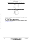
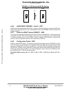
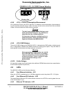
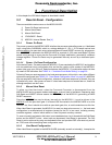
FIGURE 4-8 JP9 - 5V CODEC Source Selection
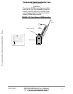
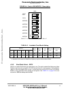
4•3•8 JS1-5 - Current Consumption Measurement
JS1-5 reside on I/O-pins, core & PLL main flow. To measure current consumption, the correspond-
ing JS should be removed using a solder tool and a current meter (shunt) should be connected
instead, with as shorted and thicker wires as possible.
Warning
The job of removing JS1-5 and soldering current
meter connections instead is very delicate and
should be done by a skilled technician.
If this process is done by unskilled hand or re-
peated more than 3 times, permanent damage
might be inflicted to the MSC8101ADS.
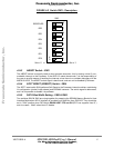
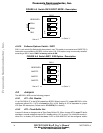
4•3•9 JG1-6 GND Bridges
There are 6 GND bridges on the MSC8101-ADS, 4, designated as GND reside on digital ground
and 2, designated as AGND3 and AGND4 resides on analog ground plane. They are meant to
assist general measurements and logic-analyzer connection.
Warning
When connecting to a GND bridge, use only IN-
SULATED GND clips. Otherwise, un-insulated
clips may cause short- circuits, touching "HOT"
points around them. Failure in doing so, might
result in permanent damage to the
MSC8101ADS.
4•3•10 Solder Bridges
All the solder bridges should be shorted while additional SDRAM device has been assembled on
the ADS board (special requirement).
4•4 LEDs
The MSC8101-ADS has the following indicators:
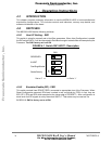
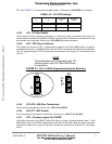
4•4•1 Fast Ethernet Indicator - LD1
When the LXT970 is enabled and is in 100 Mbps operation mode, the yellow LED - LD1 lights.
4•4•2 Fast Ethernet RX Indicator - LD2
The green Ethernet Receive LED indicator blinks whenever the LXT970 is receiving data from one
of the 10/100-Base-T port.
4•4•3 Ethernet TX Indicator - LD3
1
1
JP9 JP9
5V Internal
+5V
Factory Set
External
GND
Frees
cale Semiconductor,
I
Freescale Semiconductor, Inc.
For More Information On This Product,
Go to: www.freescale.com
nc...