


MOTOROLA MSC8101ADS RevB User’s Manual B-83
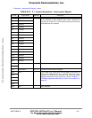
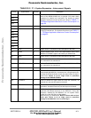
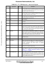
A13 SPISELb(PD19) I/O, T.S. When SPI port is enabled, this signal is the select input line for
that port. When this port is disabled, this signal may be used to
any available alternate function for PD19. In fact, for the ADS
application using as GPIO output pin.
A14 SPICLK(PD18) I/O, T.S. When SPI port is enabled, this signal is SPI clock output line for
that port. When this port is disabled, this signal may be used to
any available alternate function for PD18.
A15 SPIMOSI(PD17) I/O, T.S. When SPI port is enabled, this signal is master output line for that
port. When this port is disabled, this signal may be used to any
available alternate function for PD17.
A16-A20 N.C. - Not connected
A21 HCS2 I Chip-select 2 input for HDI16 port. Present as well as at P4
connector.
A22 HCS1 I Chip-select 1 input for HDI16 port. Present as well as at P4
connector.
A23 HRDRW I When the HDI16 is programmed to interface to a single data
strobe host bus, this pin is the read/write input (HRW). When the
HDI16 is programmed to interface to a double data strobe host
bus, this pin is the read data strobe Schmitt trigger input (HRD).
Present as well as at P4 connector.
A24 HWRDS I When the HDI16 is programmed to interface to a single data
strobe host bus, this pin is the data strobe Schmitt trigger input
(HDS). When the HDI16 is programmed to interface to a double
data strobe host bus, this pin is the write data strobe Schmitt
trigger input (HWR). Present as well as at P4 connector.
A25 PD7 MSC8101’s Port D7 Parallel I/O line. May be used to any of its
available functions
A26-A28 N.C. - Not connected
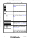
A29 ATRCKDIS I ATM Receive Clock Out Disable. When active (H), the ATMRCLK
output, on pin C29 of this connector, is Tri-stated. When either not
connected or driven low, ATMRCLK on pin C29, is enabled. This
provides compatibility with ENG revision of T/ECOM
communication tools.
A30 HOSTPD I Host tool present detect. Disable Host Interface with active low
(GND) for not compatible external tools.
A31-A32 5V P 5V Supply. Connected to ADS’s 5V VCC plane. Provided as
power supply for external tool. For allowed current draw, see
TABLE 7-1. "Off-Board Application Maximum Current
Consumption" on page 66
.
B1 ATMTXENb (PA31) I/O, T.S. ATM Transmit Enabled (L). When this signal is asserted (Low),
while the ATM port is enabled and ATMTFCLK is rising, an octet
of data, ATMTXD(7:0), is written into the transmit FIFO of the
PM5350. When the ATM port is disabled, this line may be used
for any available function of PA31.
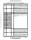
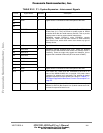
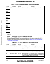
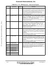
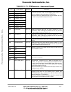
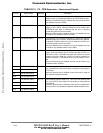
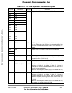
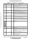
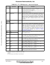
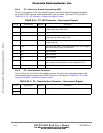
TABLE B1-3. P2 - CPM Expansion - Interconnect Signals
Pin No. Signal Name Attribute Description
Frees
cale Semiconductor,
I
Freescale Semiconductor, Inc.
For More Information On This Product,
Go to: www.freescale.com
nc...