


30 MSC8101ADS RevB User’s Manual MOTOROLA
Operating Instructions
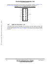
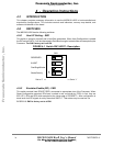
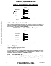
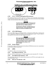
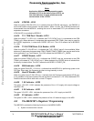
FIGURE 4-5 Switch SW10 BOOT MODE - Description
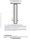
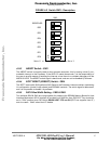
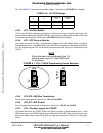
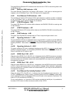
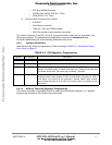
4•2•10 Software Options Switch - SW11
SW11 is a 4-switch Dip-Switch with three poles in use. This switch is connected over SWOPT(0:2)
lines which are available at BCSR2 via bus driver U16, S/W options may be manually selected,
according to SW11 state. SW11 is factory set to all ON.
FIGURE 4-6 Switch SW11 S/W Option - Description
4•3 Jumpers
The MSC8101-ADS has the following jumpers:
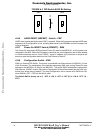
4•3•1 JP1 - DLL Disable.
J1 set DLLDIS bit 27 in the HCW loaded from BCSR. When Jumper JP1 is open MSC8101 will be
configured without DLL. If JP3 will closed the DLL is ON. Setting of JP3 is depended on jumper
JP2 (see JP2 description). Default set is JP3-OPEN (DLL disable).
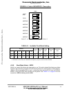
4•3•2 JP2 - Clock Buffer Set.
Jumper J2 allows to change mode of Zero-Delay Buffer JP2. When Jumper JP2 is open ZD buffer
operates in normal mode and require DLL disable setting (JP1 is open). For U44 buffer mode (in-
ternal PLL is disable) JP2 should be close. If JP2 is close MSC8101 will be configured without
SW10
ON
1
2
3
4
DBG
BTM0
BTM1
RESERVED
Set to ‘0’
<=
=> Set to ’1’
BOOT
SW11
ON
1
2
3
4
SWOPT0
SWOPT1
SWOPT2
RESERVED
Set to ‘0’
<=
=> Set to ’1’
Frees
cale Semiconductor,
I
Freescale Semiconductor, Inc.
For More Information On This Product,
Go to: www.freescale.com
nc...