


MOTOROLA MSC8101ADS RevB User’s Manual VII
LIST OF FIGURES
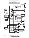
FIGURE 1-1 MSC8101ADS Block Diagram 15
FIGURE 2-1 MSC8101ADS Top Side Part Location diagram 17
FIGURE 3-1 Host System Debug Scheme A 19
FIGURE 3-2 Host System Debug Scheme B 20
FIGURE 3-3 Stand Alone Configuration 21
FIGURE 3-4 P26: +5V Power Connector 21
FIGURE 3-5 P6 - JTAG/OnCE Port Connector 22
FIGURE 3-6 P4 - Host I/F Connector 23
FIGURE 3-7 P27A - Upper RS-232 Serial Port Connector 24
FIGURE 3-8 P27B - Lower RS-232 Serial Port Connector 24
FIGURE 3-9 Flash Memory SIMM Insertion 25
FIGURE 4-1 Switch SW1 HOST - Description 26
FIGURE 4-2 Switch SW2 - Description 27
FIGURE 4-3 DIP-Switch 64/32 Bit Setting 28
FIGURE 4-4 Switch SW9 MODCK - Description 29
FIGURE 4-5 Switch SW10 BOOT MODE - Description 30
FIGURE 4-6 Switch SW11 S/W Option - Description 30
FIGURE 4-7 JP4 - FLASH Programming Source Selection 31
FIGURE 4-8 JP9 - 5V CODEC Source Selection 32
FIGURE 5-1 Clock Distribution Scheme 43
FIGURE 5-2 SDRAM Connection Scheme 45
FIGURE 5-3 FLASH SIMM Connection Scheme 47
FIGURE 5-4 MSC8101 to CODEC connection. 51
FIGURE 5-5 RS232 Serial Ports’ Connector 52
FIGURE 5-6 Host Interface Diagram 53
FIGURE 7-1 ADS Power Scheme 65
Frees
cale Semiconductor,
I
Freescale Semiconductor, Inc.
For More Information On This Product,
Go to: www.freescale.com
nc...