


56 MSC8101ADS RevB User’s Manual MOTOROLA
Functional Description
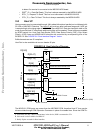
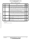
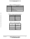
5•11•2 BCSR1 - Board Control / Status Register 1
The BCSR1 serves as a control register on the ADS. It is accessed as a word at offset 4 from
BCSR base address. It may be read or written at any time. BCSR1 gets its defaults upon Power-
On reset. BCSR1 fields are described in TABLE 5-10. "BCSR1 Description" below
2HOSTTRI Host Request or Acknowledge Enable. When high host request/
acknowledge I/O obtains high impedance and external buffer is HI-Z if low
this signal is enable via external buffer.
1 R,W
3 T1_1EN
a
T1/E1 channel 1 Enable. When asserted (low) T1/E1 QFALC framer
channel 1 lines are connected to the CPM TDMA1 ports. If negated (high),
T1/E1 channel 1 is disable and associated TDMA1 lines may be used for
the CODEC application. See
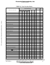
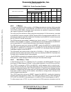
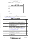
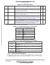
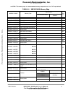
TABLE 5-11. "Peripheral’s Availability
Decoding."
for more explanation
1 R,W
4 T1_234EN
a
T1/E1 Ports channels 2,3,4 Enable. When asserted (low) the QFALC
channels 2,3,4 are available on TDMB2,TDMC2 and TDMD2. When
negated (high), the QFALC channels 2,3,4 are isolated by tri-state buffers
b
.
The T1/E1 2,3,4 ports are available when MII bus of Fast Ethernet
Transceiver is disabled. See TABLE 5-11. "Peripheral’s Availability
Decoding."
for more explanation.
1R,W
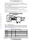
5FRM_RST
T1/E1 Framer (QFALC) Reset. When asserted (low), the QFALC device is
in reset state. This line is driven also by HRESET~ signal of the MSC8101.
1 R,W
6 SIGNAL_LAMP_0
Signal Lamp 0. When this signal is active (low), a dedicated Green LED
illuminates. When in-active, this LED is darkened. This LED may be used
for S/W signalling to user.
1 R,W
7 SIGNAL_LAMP_1 Signal Lamp 1. When this signal is active (low), a dedicated Red LED
illuminates. When in-active, this LED is darkened. This LED may be used
for S/W signalling to user.
1 R,W
a. See also TABLE 5-11. "Peripheral’s Availability Decoding."
b. In fact only “Receive Data Out” and “Receive Clock” output signals from QFALC will be disabled. “Frame Sync”
should be disabled by QFALC programming or by reset to the framer (
FRM_RST bit).
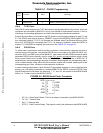
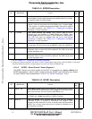
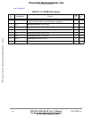
TABLE 5-10. BCSR1 Description
BIT MNEMONIC Function
PON
DEF
ATT.
0 SBOOT_EN Serial BOOT Enable. When asserted (low) or if serial boot mode is chosen
I2C lines are tied to EEPROM part U20, if
(high) FETH MII data bus are
driven over I2C lines. The mux is done via Bus Switch U19.
0 R,W
1CODEC_EN
a
CODEC Enable. When asserted (low) CODEC chip (CS4221) is connected
to TDMA1 port, if (high) data path from CODEC is isolated.
0 R,W
2ATM_EN ATM Port Enable. When asserted (low) the ATM UNI chip (PM5350)
connected to FCC1 is enabled for transmission and reception. When
negated, the ATM transceiver is in fact
b
in standby mode and its associated
buffers
c
are in tri-state mode, freeing all its i/f signals for off-board use via
the expansion connectors.
1R,W
TABLE 5-9. BCSR0 Description
BIT MNEMONIC Function
PON
DEF
ATT.
Frees
cale Semiconductor,
I
Freescale Semiconductor, Inc.
For More Information On This Product,
Go to: www.freescale.com
nc...