


MOTOROLA MSC8101ADS RevB User’s Manual 53
Functional Description
to detect if a terminal is connected to the MSC8101ADS board.
•DSR
A
( O ) - Data Set Ready. This line is always asserted by the MSC8101ADS.
• RTS ( I ) - Request To Send. This line is not connected in the MSC8101ADS.
• CTS ( O ) - Clear To Send. This line is always asserted by the MSC8101ADS.
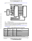
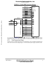
5•9 Host I/F
Host processor may be connected through 16bit-wide
B
bidirectional parallel port multiplexed with
32 LSB
C
of MSC8101 Data bus. The Host I/F will be driven after hard-reset sequence if HPE pin
is sampled high at the rising edge of PORESET
. Since MSC8101 Data bus has 64bit width in 60x
mode to provide Host I/F disconnect additional buffers will be needed. These buffers are enabled
by BCSR control line. Host Dual Data Strobe (DDS), Data Strobe Polarity (DSP), Chip Select
Polarity (CSP) lines and HRRQ/HACK direction are controlled by corresponding bits of the
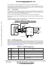
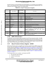
BCSR0/1-2. See FIGURE 5-6 "Host Interface Diagram" below.
Buffer/transceivers are 5V compliant.
Host Port is also available via two row header 36 pins.
FIGURE 5-6 Host Interface Diagram
The MSC8101 CPM ports are poorer than the MPC8260 CPM, therefore Host I/F bus may be
driven outside through CPM Expansion Connector in place of unusable lines. Since the CPM Ex-
A. Since there are only 3 RS232 transmitters in the device, DSR is connected to CD.
B. 8-bit mode is also available for HDI8 I/F.
C. Really 28pins are used for Host interface.
D[0:63]
D[32:47]
HD[0:15]
16bit
PPC bus
D[55]
HREQ/HTRQ
D[56]
HACK/HRRQ
DIR
DIR
from BCSR control bit set once
from BCSR
D[48:51]
HA[0:3]
D[52:54]
HCS,HRW,HWR
E
E
E
E
To P2-CPM & P4-HOST conn
BCSR controlled
Presence Detect Pin (PDP)
O.D.
O.D.
D[57:60]
DSP, DDS,
8BIT
PORESET
O.D.
Host Enable
DIP SW
To P2 & P4 conn.
HRESET
O.D.
U45
U3
U4
U45
Frees
cale Semiconductor,
I
Freescale Semiconductor, Inc.
For More Information On This Product,
Go to: www.freescale.com
nc...