


52 MSC8101ADS RevB User’s Manual MOTOROLA
Functional Description
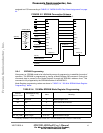
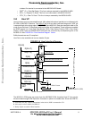
5•8•4 T1/E1 Ports
The QFALC framer supports four T1/E1 and contains analog and digital function blocks, which are
configured and controlled by MSC8101. Due to its multitude of implemented functions, it fits to a
wide range of networking applications and fulfills the according international standards
.
External clock oscillator is mounted on the DIP socket to provide easy changing for both T1 and
E1. The QFALC reset input is driven by FRMRST~ signal of the BCSR0/5. Due the MSC8101 I/O
pins functional limitation, T1/E1 2,3,4 channels are available when Fast Ethernet MII pins will be
set to Hi-Z (FETHIEN bit is asserted) and T1/E1 1-th channel is available, when the CODEC is
disable (T1_234CODEN is negated) and vice versa. See TABLE 5-6. on page 49.
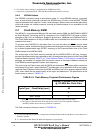
5•8•5 RS232 Ports
To assist user’s applications and to provide convenient communication channels with both a
terminal and a host computer, two identical RS232 ports is provided on the MSC8101ADS, con-
nected to SCC1 and SMC1 ports of the MSC8101. Use is done with MC145583 transceiver which
generates RS232 levels internally using a single 3.3V supply and has shutdown mode, during
which receive buffers are tri-stated. When the RS232EN1
or RS232EN2 bits in BCSR1/6-7 is
asserted (low), the corresponding transceiver is enabled. When negated, the corresponding trans-
ceiver is enter standby mode, within which the receiver outputs are tri-stated, enabling use of the
corresponding port’s pins, off-board via the expansion connectors.
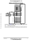
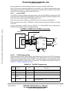
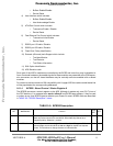
In order of saving board space, 9 pins, female D-Type stacked connector is used, configured to be
directly (via a flat cable) connected to a standard IBM-PC like RS232 connector.RS-232 Ports’
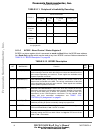
Signal Description the list below, the directions ’I’, ’O’, and ’I/O’ are relative to the MSC8101ADS
board. (I.e. ’I’ means input to the MSC8101ADS).
FIGURE 5-5 RS232 Serial Ports’ Connector
• CD ( O ) - Data Carrier Detect. This line is always is asserted by the MSC8101ADS.
• TX ( O ) - Transmit Data.
• RX ( I ) - Receive Data.
• DTR ( I ) - Data Terminal Ready. This signal is used by the software on the MSC8101ADS
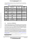
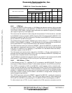
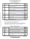
6 Converter Status - Read only
7 Master Clock ‘0’ Default. Crystal frequency is equal to 256x Fs
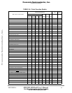
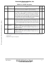
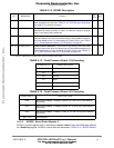
TABLE 5-7. CS4221 Programming
Byte
Num.
Function Value Meaning:
1
RX
2TX
3
RTS
4
CTS
5
DSR6
GND
7
DCD
8
9N.C.
DTR
Frees
cale Semiconductor,
I
Freescale Semiconductor, Inc.
For More Information On This Product,
Go to: www.freescale.com
nc...