


MOTOROLA MSC8101ADS RevB User’s Manual 29
Operating Instructions
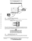
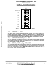
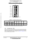
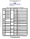
FIGURE 4-4 Switch SW9 MODCK - Description
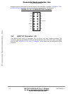
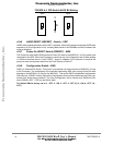
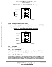
4•2•9 Boot Mode Select - SW10
SW10 is a 4-switch Dip-Switch with three poles in use. This switch selects Boot Mode over Altera
FPGA on the Processor inputs EE0, EE4, EE5 during Power-On reset sequence. Setting SW10/1
(DBG) to ON brings holding EE0 at logic 1 during reset that puts the SC140 core into DEBUG
MODE. In doing so BTM’s switch position will be ignored. See TABLE 5-1 on page 40 for more
explanation. SW10 is factory set to all ON.
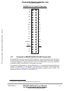
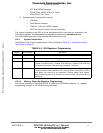
TABLE 4-1. Available Clock Mode Setting
MODCK-
Clock
Mode
Clock In
MHz
CPM
MHz
PPC Bus
MHz
SC140 Core
MHz
-1 -2 -3 -4 -5 -6
0 0 1 1 1 1 57
a
55 137.5 55
a
a. Factory setting.
275
0010019
b
b. Alternative clock mode for 100MHz bus frequency requires clock oscillator 20MHz
20 200 100 300
SW9
ON
1
2
3
4
MODCK1
MODCK2
MODCK3
5
6
7
8
MODCK4
MODCK5
MODCK6
FCFG
CFG
Set to ‘0’
<=
=> Set to ’1’
HOST
Frees
cale Semiconductor,
I
Freescale Semiconductor, Inc.
For More Information On This Product,
Go to: www.freescale.com
nc...