


66 MSC8101ADS RevB User’s Manual MOTOROLA
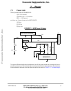
Power
cation Maximum Current Consumption" below:
To protect on-board devices against supply spikes, decoupling capacitors (typically 0.1µF) are
provided between the devices’ power leads and GND, located as close as possible to the power
leads, while 47 µF bulk capacitors are spread around.
7•1•1 5V Bus
Some of the ADS peripherals reside on the 5V bus. Since the MSC8101 is not 5V tolerant, buffer-
ing is provided between 5V peripherals and the MSC8101, protecting the MSC8101 from the
higher voltage level. The 5V bus is connected to an external power connector via a fuse (4A).
To protect against reverse-voltage or over-voltage being applied to the 5V inputs a set of high-
current diodes and zener diode is connected between the 5V bus GND. When either over or
reverse voltage is applied to the ADS, the protection logic blows the fuse, while limiting the mo-
mentary effects on board.
7•1•2 3.3V Bus
The MSC8101, the SDRAMs, the address and data buffers are powered by the 3.3 bus, which is
produced from the 5V bus using a low-voltage drop, linear voltage regulator LM1085S, the which
is capable of driving upto 4A, facilitating operation of external logic as well.
7•1•3 1.5V Bus
The MSC8101’s internal logic and the PLL are powered with a lower-voltage power source, voltage
of which may be in a range of 0.9V - 2.2V. Obviously, there is the power-speed trade-off, i.e., lower
operation speeds may be obtained with lower voltage supply.
To provide means of evaluating this trade-off, a variable, linear power regulator - MIC29372 with
OpAmp MC33202 in feedback, is provided, so that the voltage level of that bus, may be easily
tuned, to evaluate influence.
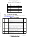
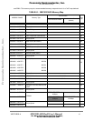
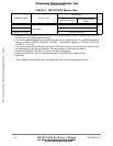
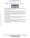
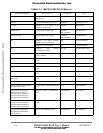
TABLE 7-1. Off-Board Application Maximum Current Consumption
Power Bus Max. Current
5V0 2A
3V3 1.5A
Frees
cale Semiconductor,
I
Freescale Semiconductor, Inc.
For More Information On This Product,
Go to: www.freescale.com
nc...