


B-82 MSC8101ADS RevB User’s Manual MOTOROLA
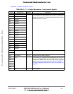
B•1•2 MSC8101ADS’s P2 - CPM Expansion Connector
P4 is a 128 pin, 90
0
, DIN 41612 connector, which allows for convenient expansion of the
MPC8101’s serial and host ports. This connector contains all CPM pins plus power supply pins, to
provide for easy tool connection. The pinout of P2 is shown in TABLE B1-3. "P2 - CPM Expansion
- Interconnect Signals" below:
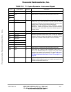
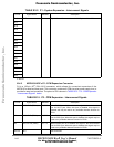
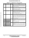
D16 GND P Digital Ground. Connected to main GND plane of the ADS.
D17
D18
D19
D20
D21
D22
D23
D24
D25
D26
D27
D28
D29
D30
D31
D32
a. MS Bit.
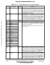
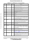
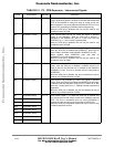
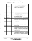
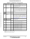
TABLE B1-3. P2 - CPM Expansion - Interconnect Signals
Pin No. Signal Name Attribute Description
A1 SCC1RXD (PD31
a
) I/O, T.S. When RS232 port #1 is enabled, this signal is the receive data
line for SCC1 port. When this port is disabled, this signal is
tristated and may be used to any available alternate function for
PD31.
A2 SCC1RXD (PD30) I/O, T.S. When RS232 port #1 is enabled, this signal is the transmit data
line for SCC1 port. When this port is disabled, this signal may be
used to any available alternate function for PD30.
A3 SCC1CTSb (PD29) I/O, T.S When RS232 port #1 is enabled, this signal is the carrier detect
line for SCC1 port. When this port is disabled, this signal may be
used to any available alternate function for PD29.
A4-A12 N.C. - Not connected
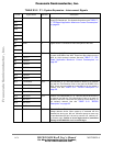
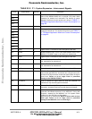
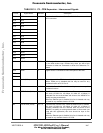
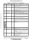
TABLE B1-2. P1 - System Expansion - Interconnect Signals
Pin No. Signal Name Attribute Description
Frees
cale Semiconductor,
I
Freescale Semiconductor, Inc.
For More Information On This Product,
Go to: www.freescale.com
nc...