


MOTOROLA MSC8101ADS RevB User’s Manual 31
Operating Instructions
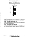
DLL. See TABLE 4-2. summarized available modes. . Default set is JP3-OPEN (DLL disable).
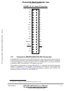
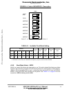
4•3•3 JP3 - 50 Ohm Enable.
JP3 provides 50 Ohm resistance termination in case when using an external clock source via
coaxial cable connected to the SMB CLOCKIN. In so doing the on-board clock oscillator U18 must
be removed from the socket. Default set is JP3-OPEN (termination disable).
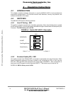
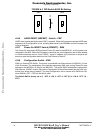
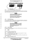
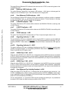
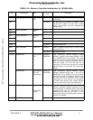
4•3•4 JP4 - VPP Source Selector
JP4 selects the source for VPP - programming voltage for the Flash SIMM. When a jumper is
located between pins 1 - 2 of JP4 (Factory Set), the VPP is connected to the 5V0 plane of the ADS.
For 12V programming set VPP will be drawn from external power supply 12V connected to pins
JP4/2,3.
NOTE
Should be taken into consideration that 12V
external power input for Flash SIMM have
no protection.
FIGURE 4-7 JP4 - FLASH Programming Source Selection
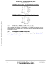
4•3•5 JP5,JP8 - 600 Ohm Termination.
Set for audio measurements. Factory set - JP5,JP8 are OPEN.
4•3•6 JP6,JP7 - MIC Enable.
Set if using external microphone audio source. Factory set - JP6,JP7 are CLOSE.
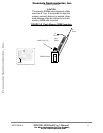
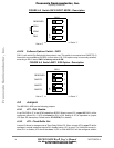
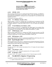
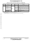
4•3•7 JP9 - 5V power supply for CODEC
JP9 selects the source for CODEC Power Rail. When a jumper is located between pins 1 - 2 of
JP9 (Factory Set), the CODEC feeds from the 5V0 plane of the ADS. When a jumper is removed
external low noise power supply 5V @ 200 mA might be connected to JP9 pins 2,3. See figure
below:
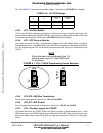
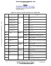
TABLE 4-2. JP1/JP2 Settings
J1 J2
Clock Driver
U44
MSC8101
Mode
OPEN OPEN PLL Mode DLL disable
CLOSE CLOSE Buffer Mode DLL enable
1
JP4
5V
Factory Set
1
JP4
12V Ext.
+
-
Frees
cale Semiconductor,
I
Freescale Semiconductor, Inc.
For More Information On This Product,
Go to: www.freescale.com
nc...