


85
Connecting to the Host’s RS-232C Port Section 5-1
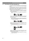
Usable Cables with Attached Connectors:
• For host link, 1:1 NT Link, or 1:N NT Link (+5 V power supplied from PLC)
XW2Z-070T-1(9-pin to 9-pin, 0.7 m)
XW2Z-200T-1(9-pin to 9-pin, 2 m)
CVM1/CV-series CPU Units whose model names do not have the suffix -EV@
cannot be connected by any connection method.
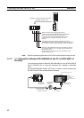
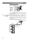
When connecting to the peripheral port of a CS/CJ-series CPU Unit, a CS1W-
CN118 Connecting Cable is required in addition to the above cables. (Supply
power to the +5-V output of the NT-AL001 from an external power supply
when using this method.)
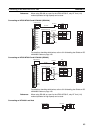
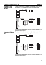
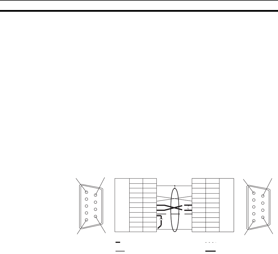
• When using the host link or NT Link (1:1) method, short the RS and CS
terminals at the PLC side with each other (leave the RS and CS terminals
at the NT-AL001 side open).
• When using the NT Link (1:N), cross-connect the RS and CS terminals at
the NT-AL001 and PLC sides.
If there is +5 V output at the PLC side, no external power supply is re-
quired for the NT-AL001.
C200HE-CPU32/42(-Z)E
C200HG-CPU33/43/53/63(-Z)E
C200HZ-CPU34/44/54/64(-Z)E
C200HX-CPU65-ZE C200HX-CPU85-ZE
CV500-CPU01-EV1 CV1000-CPU01-EV1
CV2000-CPU01-EV1
CVM1-CPU01-EV2 CVM1-CPU11-EV2
CVM1-CPU21-EV2
SRM1-C02-V2
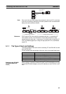
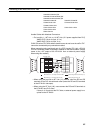
Shielding wire
(9-pin type)
NT-AL001 side PLC side
(9-pin type)
1
6
5
9
1
6
5
9
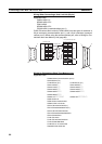
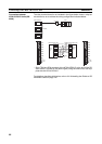
When there is no +5 V output at the PLC side
When there is +5 V output at the PLC side
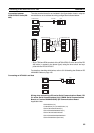
When using host link or NT Link (1:1)
When using NT Link (1:N)
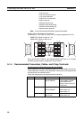
Abbreviation Pin number
Pin number
Abbreviation
RS-232C
connector
Connector
hood
RS-232C
connector
Connector
hood
1
2
3
4
5
6
7
8
9
FG
−
SD
RD
RS
CS
+5V
−
−
SG
FG
−
SD
RD
RS
CS
+5V
−
−
SG
1
2
3
4
5
6
7
8
9