


63
Connecting to the RS-232C Port at the Host Section 4-1
*1
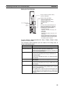
One of the following Communications Boards is required: C200HW-
COM02/COM04/COM05/COM06-EV1.
*2
A CPM1-CIF01 Adapter is required.
*3
Use a CPM2C-CN111 or CS1W-CN114/118 Connecting Cable, CPM1-
CIF01 RS-232C Adapter, or CPM1-CIF11 RS-422A Adapter to connect.
*4
A CQM1H-SCB41 Serial Communications Board is required.
*5
CPU Units of CVM1/CV-series PLCs without the suffix -EV@ cannot be
connected.
Reference: CS/CJ-series CPU Units cannot be connected with the 1:1 connection NT link
method. Use the 1:N connection NT link method (standard or high-speed)
instead to make the 1:1 connection. For details, refer to Using the NT Link
(1:N) Method (page 65) or Using the High-speed NT Link (1:N) Method
(page 70).
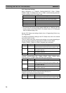
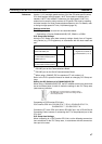
Settings at the Host
The setting methods for each Unit are as follows.
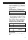
Connecting to a C-series C200HS, C200HX/HG/HE(-Z)E, CPM1, CPM2A,
CPM2C, CQM1, CQM1H or SRM1 PLC
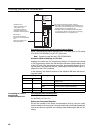
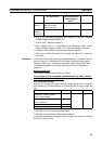
PLC Setup Area Settings
Write the PLC Setup area (data memory) settings directly from a Program-
ming Device (e.g. CX-Programmer) in accordance with the host model and
port.
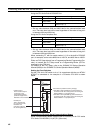
*1
RS-232C port of the Communications Board
*2
RS-232C port of the Serial Communications Board
For details on operations relating to the PLC Setup area, refer to the manual
for the PLC which is used.
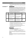
CVM1
Series
(*5)
CVM1-CPU01-EV2
CVM1-CPU11-EV2
CVM1-CPU21-EV2
CVM1
CompoBus/
S Master
Control Unit
SRM1-C02-V1 SRM1
PLC Series CPU Units with Built-in
NT Link Function
CPU Units Connect-
able with Expansion
Communications
Board
(*1)
Connectable to
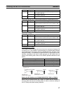
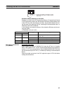
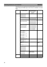
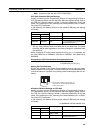
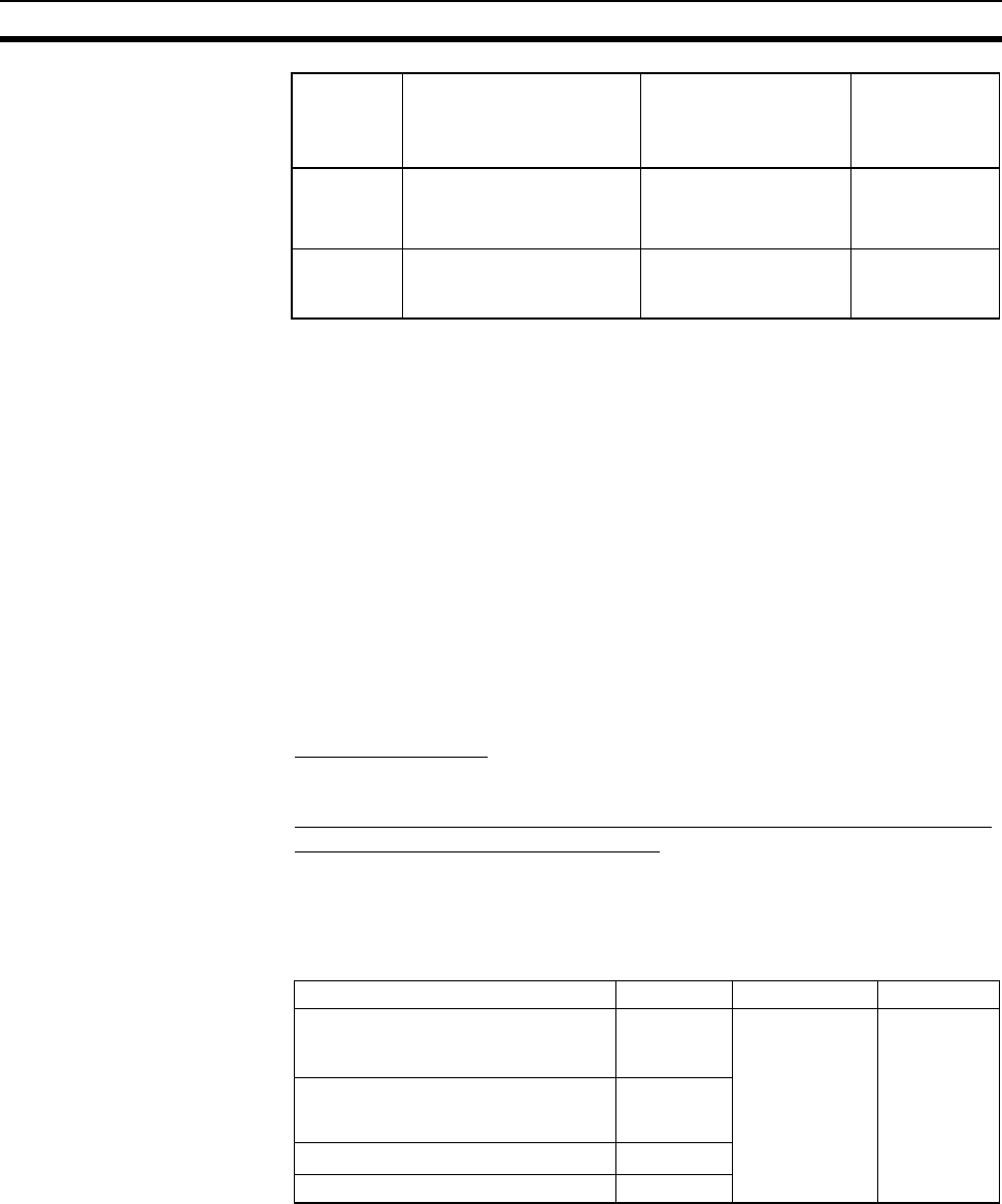
Host Model Word # Writing Value Setting
RS-232C port of C200HS, C200HX/
HG/HE(-Z)E, CPM2A, CPM2C,
CQM1, CQM1H, SRM1
DM6645 4000 Use NT link
(1:1)
Port A of C200HX/HG/HE(-Z)E
(*1)
Port 1 of CQM1H
(*2)
DM6555
Port B of C200HX/HG/HE(-Z)E
(*1)
DM6550
CPM1 DM6650