115
Connecting to the Host’s RS-422A/485 Port Section 5-2
The following are the communications conditions that can be used with the
memory link method. For the host (a personal computer, an FA computer,
etc.), its setting should be compatible to one of the communications condi-
tions listed in the following table. Set the same communications conditions at
the NT631/NT631C by the memory switch. (page 160).
5-2-2 Direct Connection between RS-422A Ports at Both Units
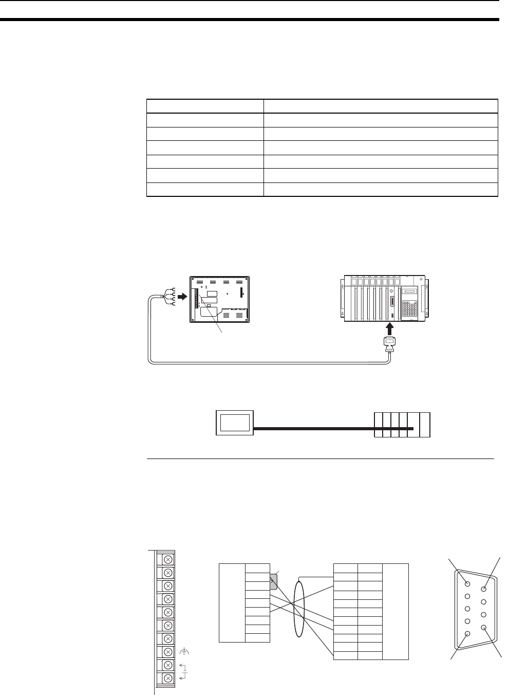
The connection method in which the RS-422A ports of an NT631/NT631C
and a host are connected is described here.
Connecting an NT631/NT631C and Host (RS-422A)
Wiring When Connecting a C-series Host Link Unit or CPM1 (Host Link)
Applicable Units:
For details on handling shield wires, refer to 5-2-8 Handling the Shield on RS-
422A/485 Cables on page 125.
Item Setting at Host
Input/Output board RS-422A
Communications speed 1200, 2400, 4800, 9600, 19200, 38400 bps.
Data bits length 7 bits, 8 bits
Stop bits length 1 bit, 2 bits
Parity None, even, odd
Flow control None, XON/XOFF
NT631/NT631C
RS-422A cable with connectors
(
max. len
g
th: 500 m
)
+DC
RESET
RDA
TRM
RDB
SDA
SDB
CSA
CSB
PRI NTER
PORT B
PORTA
24V
Host Link Unit, CPU Unit,
Communications Unit/Board
Serial port B
(RS-422A/485, terminal block)
SYSMAC
CS/CJ-series PLC,
C-series PLC,
CVM1/CV series
PLC, SRM1
9-pin connector or
25-pin connector
C200H-LK202-V1
3G2A5-LK201-EV1
C500-LK203
3G2A6-LK202-EV1
NT631/NT631C
RS-422A
Host
NT631/NT631C side
6
5
9
1
PLC side
(9-pin type)
Pin number
1
2
3
4
5
6
7
8
9
Abbreviation
FG
RDB (+)
−
SG
−
SDB (+)
RDA (-)
FG
−
Abbreviation
RDA (-)
TRM
RDB (+)
SDA (-)
SDB (+)
RSA (-)
RSB (+)
RDA
TRM
RDB
SDA
SDB
RSA
RSB
24V
+DC
Shielding wire
Short-circuit tool
RS-422A/
485
terminal
block
RS-422A
terminal
block
Functional
ground
Connector
hood
Functional
ground


