


73
Connecting to the RS-232C Port at the Host Section 4-1
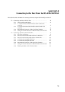
Word m = DM30000 + (100 × unit number)
When Using the Memory
Link Method
In the memory link method, the connection can be made to a personal com-
puter with RS-232 and an FA computer, etc.
When connecting to the host in the memory link method, it is necessary to
create a program for the memory link at the host side.
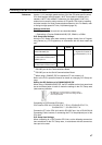
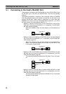
The following are the communications conditions that can be used in the
memory link method. For the host (a personal computer, an FA computer,
etc.), its setting should be compatible to one of the communications condi-
tions listed in the following table. Set the same communications conditions at
the NT631/NT631C by the memory switch. (page 160).
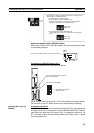
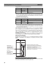
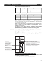
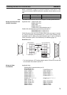
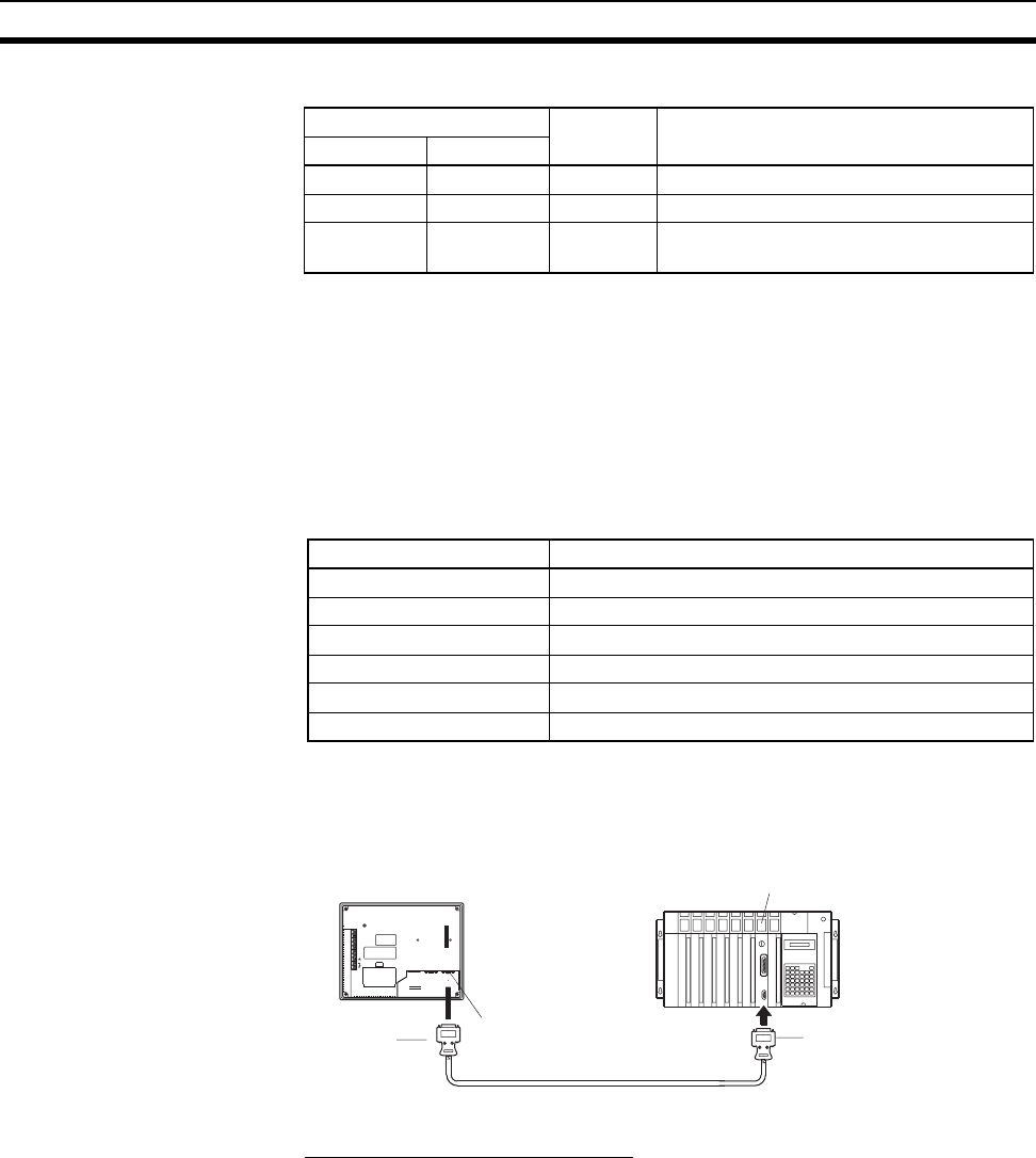
4-1-2 Connecting Directly between RS-232C Ports
The method for connection between the RS-232C ports of the NT631/
NT631C and the host is described here.
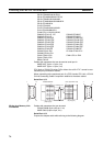
Recommended Connector Cable
When making the connector cable, as far as possible use the recommended
connectors, connector hoods, and cables indicated in the table below. Some
Units come supplied with one connector and one connector hood.
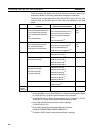
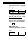
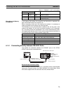
Allocated DM Area words Setting Setting Contents
Port 1 Port 2
m m+10 8200 1:N NT Link Mode
m+1 m+11 000A Baud rate (standard)
m+6 m+16 000@ @ = The highest unit number of the con-
nected PTs (0 to 7)
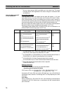
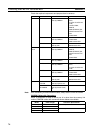
Item Settings at the host
Input/Output port RS-232C
Communications speed 1200, 2400, 4800, 9600, 19200, 38400 bps.
Data bits length 7 bits, 8 bits
Stop bits length 1 bits, 2 bits
Parity None, even, odd
Flow control None, RS/CS, XON/XOFF
+DC
RESET
RD
TRM
RDB
SDA
SDB
CSA
CSB
24V
PRINTER PORT B
PORT A
Host Link Unit or CPU Unit
NT631/NT631C
9-pin connector
Cable with RS-232C connectors
Serial port A or B
(RS-232C, 9-pin type)
SYSMAC
CS/CJ-series PLC,
C-series PLC,
CVM1/CV-series PLC,
SRM1
9-pin connector
or
25-pin connector