


152
Setting Conditions for Communications with Host by Using Memory Switches Section 6-7
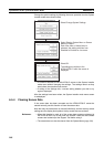
• Screen data transmission is stopped by operation at the Support Tool.
Note When transferring the data in units of screens, if there are changes in memory
table and/or direct access, transfer such data along with the screen data.
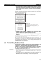
6-7 Setting Conditions for Communications with Host by
Using Memory Switches
The NT631/NT631C can be connected to the host by the following 7 types of
communications methods can be used to communicate with a host.
• Host link • Memory link method
• NT Link (1:1) • Mitsubishi A-computer link method
• NT Link (1:N) • Mitsubishi FX method
• High-speed NT Link (1:N)
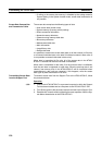
The NT631/NT631C has the following two ports, either of which can be used
for communications with the host, depending on the requirements.
• Serial port A (exclusively for RS-232C, 9-pin connector)
• Serial port B (RS-232C/RS-422A (selectable), 25-pin connector)
The method for setting the communications method for communications with
the host is described here.
For details on setting the communications conditions for a bar code reader,
refer to 6-10 Setting the Bar Code Reader Input Function.
Reference: • Apart from the host, it is also possible to connect the Support Tool or a
bar code reader to serial port A. When a bar code reader is connected at
serial port A, the host must be connected at serial port B. When serial
port A is being used for communications with the host, the host must be
disconnected so that the Support Tool can be connected.
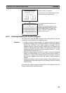
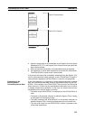
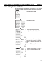
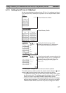
• There are four memory switch setting screens. The conditions for commu-
nications with the host are set on the fourth screen (the screen on which
4/4 is displayed). For details on setting memory switches other than those
for setting the conditions for communications with the host, refer to 6-9
Various System Settings.
• When using the Mitsubishi A-computer link method and Mitsubishi FX
method, a system program for multi-venders is required. Install the sys-
tem program to the NT631/631C by the system installer (refer to
page 145). For details, refer to PLC Connection Manual (V042-E1-@).
• When using PLCs manufactured by Allen-Bradley, GE Fanuc, or Siemens,
refer to NT31/631 Multi Vendor Connection Manual (V060-E1-@).
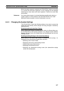
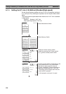
6-7-1 About Communications Conditions
Items Set for
Communications
Conditions
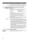
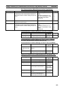
The following settings are made for the communications conditions for com-
munications between the NT631/NT631C and the host.