


65
Connecting to the RS-232C Port at the Host Section 4-1
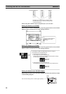
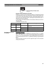
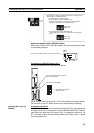
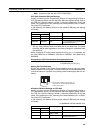
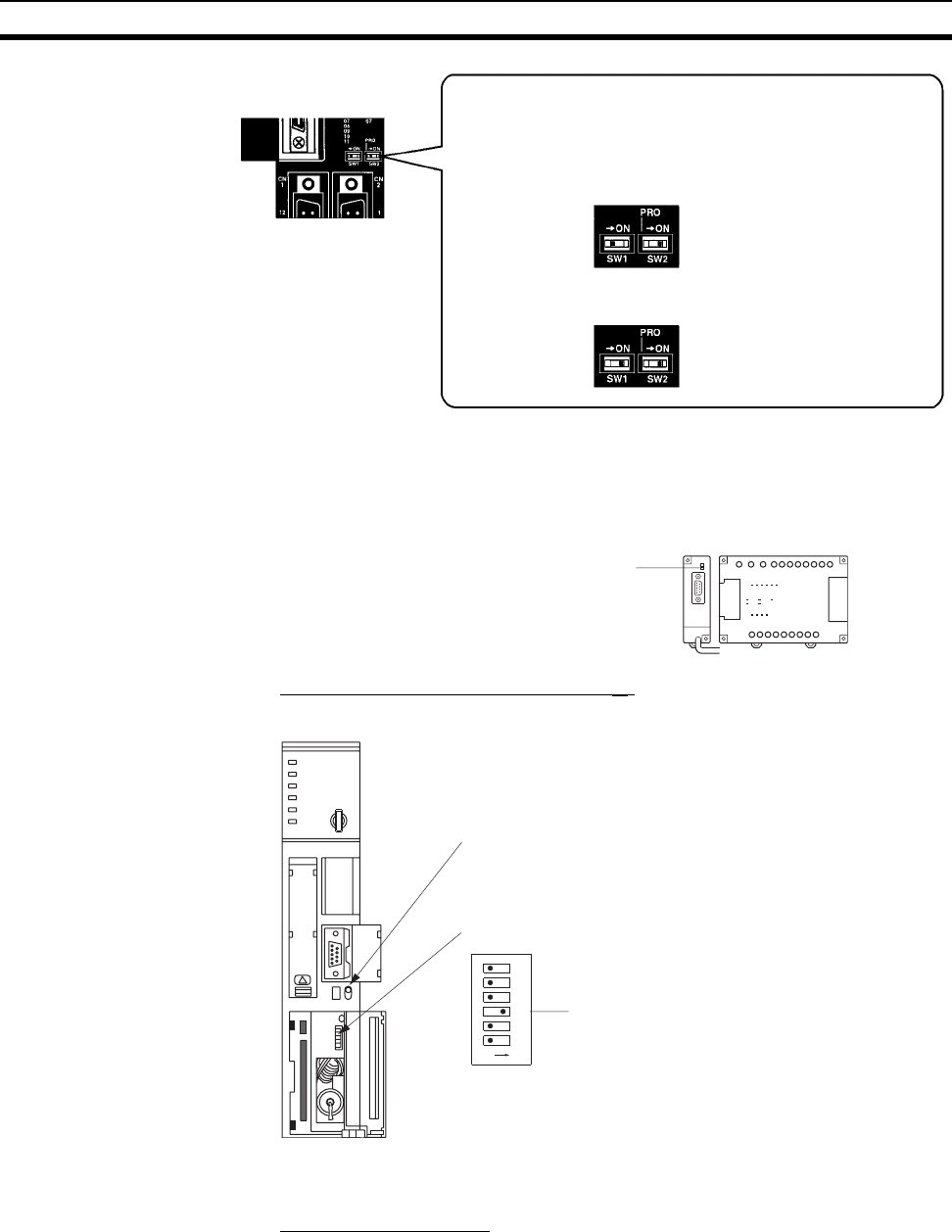
Setting the Switches on an RS-232C Adapter
When using a CPM1-CIF01 RS-232C Adapter, set the mode switch as shown
in the following diagram.
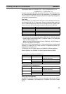
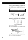
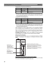
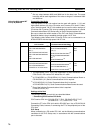
Connecting to CVM1/CV Series (-EV
@)
Set the DIP switches on the front panel as follows.
When using a CVM1/CV-series PLC, CPU Unit execution processing (execu-
tion control 2) in the PLC Setup must be set to Simultaneous processing.
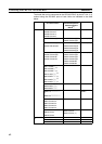
Using the NT Link (1:N)
Method
Compatible Host Units
The OMRON PLCs that can be connected using the NT link (1:N) method are
the CS/CJ-series CPU Units and the C-series C200HX/HG/HE(-Z)E, CQM1H,
and SRM1 only. With the CS/CJ-series PLCs, it is possible to connect a 1:N
NT Link using a Serial Communications Board (CS Series only) or a Serial
Communications Unit.
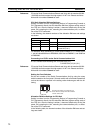
• Connecting PT to peripheral port
• Connecting PT to built-in RS-232C port
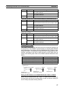
SW1: OFF
SW2: ON
• Connecting PT to built-in RS-232C port
SW1: OFF
SW2: OFF
The settings for SW1 and SW2 depend upon the usage of the
peripheral port and RS-232C port.
(A device that requires non-standard communications
settings is connected to the peripheral port.)
(A Programming Console is connected to the peripheral
port.)
Set the mode setting switch to NT (lower position).
CPM1-
CIF01
OFF
ON
1
2
3
4
5
6
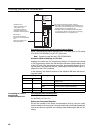
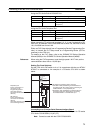
I/O port selection (selector switch)
Set this to RS-232C.
Set SW3 to use NT Link
(ON, right side).
DIP switch setting (SW3)