


87
Connecting to the Host’s RS-232C Port Section 5-1
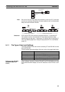
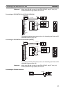
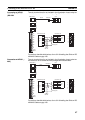
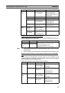
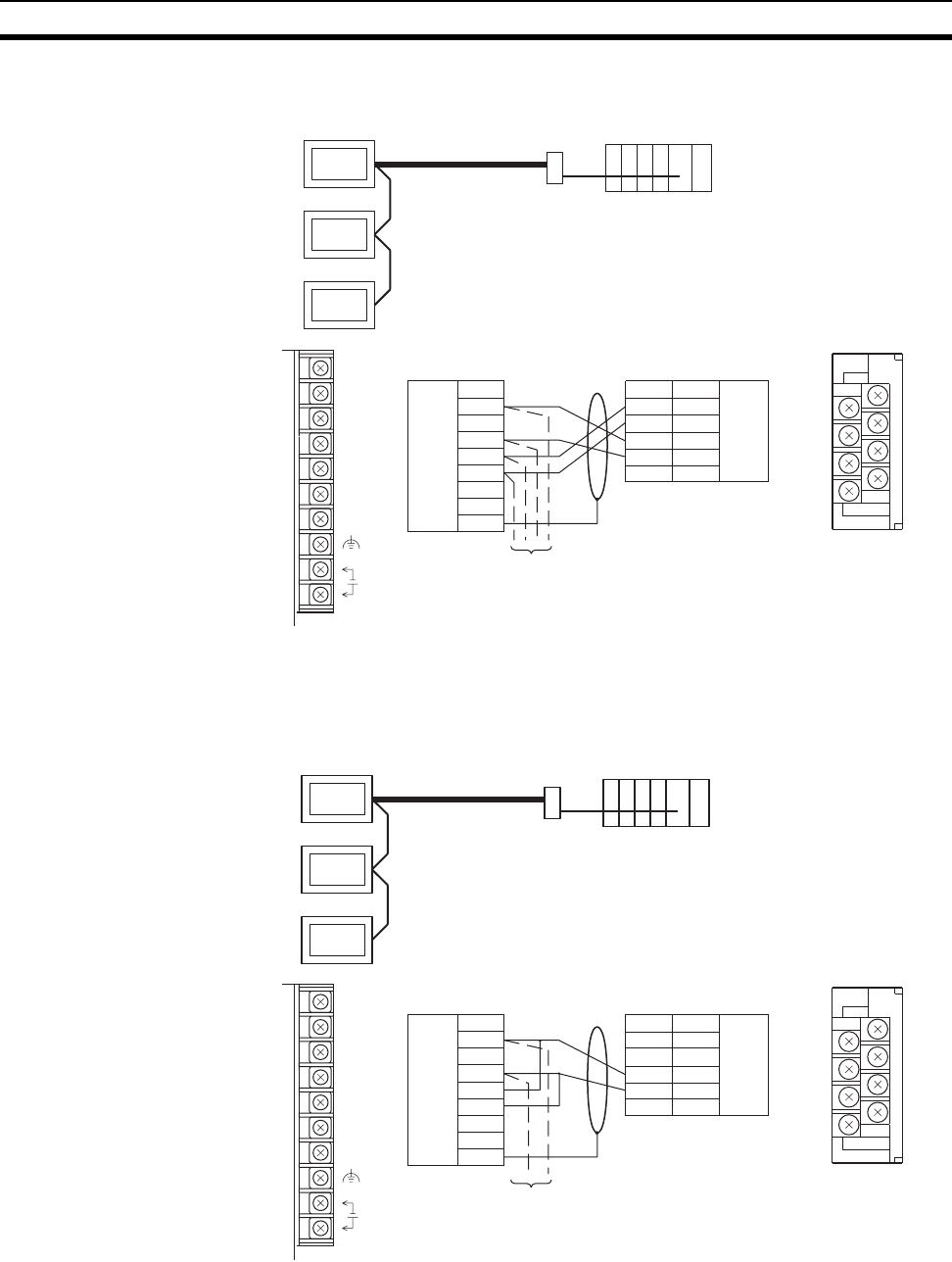
Connecting an NT631/
NT631C and NT-AL001
(RS-422A)
The relay terminal board is not included in the figure below. Insert a relay ter-
minal board so as to achieve the wiring configuration indicated below.
For details on handling shield wires, refer to 5-2-8 Handling the Shield on RS-
422A/485 Cables on page 125.
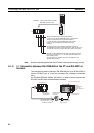
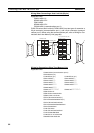
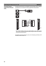
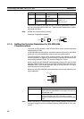
Connecting an NT631/
NT631C and NT-AL001(RS-
485)
The relay terminal board is not included in the figure below. Insert a relay ter-
minal board so as to achieve the wiring configuration indicated below.
For details on handling shield wires, refer to 5-2-8 Handling the Shield on RS-
422A/485 Cables on page 125.
Abbreviation
RDA (-)
TRM
RDB (+)
SDA (-)
SDB (+)
RSA (-)
RSB (+)
RS-422A
NT631/NT631C
Host
NT-AL001
7
5
3
1
8
6
4
2
Next PT
Pin number
6
5
4
3
1
Abbreviation
RDA (-)
RDB (+)
SDA (-)
SDB (+)
NT-AL001 side
NT631/NT631C side
Shielding wire
RDA
TRM
RDB
SDA
SDB
RSA
RSB
24V
+DC
RS-422A/
485
terminal
block
RS-422A
terminal
block
Functional
ground
Functional
ground
RS-485
NT631/NT631C
Host
NT-AL001
7
5
3
1
8
6
4
2
Next PT
NT-AL001 side
NT631/NT631C side
Shielding wire
RDA
TRM
RDB
SDA
SDB
RSA
RSB
24V
+DC
Abbreviation
RDA (-)
TRM
RDB (+)
SDA (-)
SDB (+)
RSA (-)
RSB (+)
Pin number
6
5
4
3
1
Abbreviation
RDA (-)
RDB (+)
SDA (-)
SDB (+)
RS-422A/
485
terminal
block
RS-422A
terminal
block
Functional
ground
Functional
ground