


55
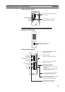
Connecting to the RS-232C Port at the Host Section 4-1
Setting the Front Switches
C-series C200HS, C200HX/HG/HE(-Z)E, CPM1, CPM2A, CPM2C, CQM1,
CPM1H CPU Units, SRM1
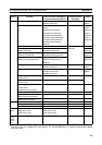
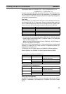
The connection method depends upon the model of PLC being used, as
shown in the following table.
PLC model Connection method
C200HS, CQM1 Connect to the CPU Unit’s built-in RS-232C port.
C200HX/HG/HE(-Z)E Connect to the CPU Unit’s built-in RS-232C port.
Connect to one of the RS-232C ports (port A or port B) on a
Serial Communications Board.
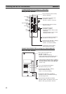
CQM1H Connect to the CPU Unit’s built-in RS-232C port.
Connect to the peripheral port through a CS1W-CN118
Connecting Cable.
Connect to the RS-232C port (port 1) on a Serial Communi-
cations Board.
CPM1 Connect to the peripheral port through a CPM1-CIF01 RS-
232C Adapter.
CPM2A, SRM1 Connect to the CPU Unit’s built-in RS-232C port.
Connect to the peripheral port through a CPM1-CIF01 RS-
232C Adapter.
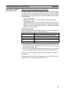
CPM2C Connect to the CPU Unit’s RS-232C port or the peripheral
port through a Connecting Cable (CPM2C-CN111, CS1W-
CN118, or CS1W-CN114).
(The CPM2C-CN111 splits the Unit’s Communications Port
into a RS-232C port and a peripheral port. A CPM1-CIF01
RS-232C Adapter is also required to connect to this periph-
eral port.)
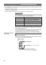
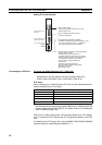
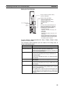
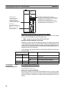
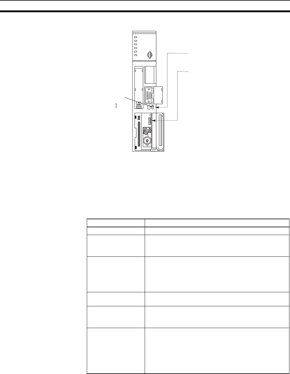
RS-232C
I/O port selector switch
RS-422A
• I/O port selection (selector switch)
Set this to RS-232C.
• System setting (DIP SW4)
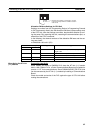
Note
- DIP switch settings:
- PLC Setup:
To effect the existing DIP switch
settings, set SW4 to ON.
To effect the existing PLC Setup,
set SW4 to OFF.
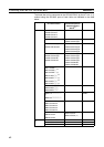
For CPU Units manufactured before or
during June 1995 (lot No. @@65), the
existing DIP switch settings differ from
the existing PLC Setup as follows.
2,400 bps, 1 stop bit, even parity, 7 bit
data length
9,600 bps, 2 stop bits, even parity, 7 bit
data length
For CPU Units manufactured from July
1995 onward (lot No. @@75), the values
specified in the DIP switch settings also
are 9,600 bps and 2 stop bits.