


105
Connecting to the Host’s RS-422A/485 Port Section 5-2
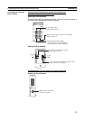
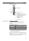
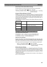
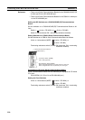
Serial Communications Board Switch Settings
Set the switches on the Serial Communications Board as shown below.
2-wire or 4-wire selector (WIRE): (4-wire = RS-422A)
Terminating resistance switch (TERM): ON (terminator ON = terminating
resistance enabled).
Allocation DM Area Settings for CPU Unit
Settings are written from the Programming Device (a Programming Console
or CX-Programmer) directly into the allocation DM area (system setting area)
of the CPU Unit. After the settings are written, they become effective by turn-
ing the power ON, restarting the Unit, restarting the communications port, or
executing the STUP command.
In the following, the channel numbers of the allocation DM area and the set-
tings are shown.
Connecting to a CS/CJ-series Serial Communications Unit
CS/CJ-series Rack-mounting Units:
CS1W-SCU31-V1 (Port 1 and port 2 are both RS-422A/485 ports.)
CJ1W-SCU31-V1 (Port 1 and port 2 are both RS-422A/485 ports.)
CJ1W-SCU41(-V1) (Port 1 is an RS-422A/485 port.)
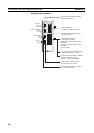
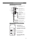
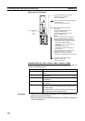
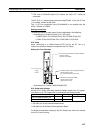
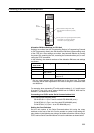
Setting the Front Switches
Set the unit number of the Serial Communications Unit using the rotary
switches on the front of the Unit. Set the number or symbol in the setting dis-
play window in the following way using a flat-blade screwdriver. When using a
CS/CJ-series Serial Communications Unit set the switches as shown below.
2-wire or 4-wire selector (WIRE): (4-wire = RS-422A)
Terminating resistance switch (TERM): ON (terminator ON = terminating
resistance enabled).
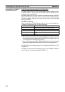
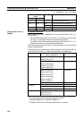
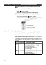
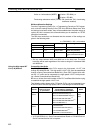
DM Area Allocation Settings
From the Programming Device (i.e., a Programming Console or CX-Program-
mer), write the settings directly to the CPU Unit's DM Area Setup Area. After
the settings have been written, they will be enabled when the power supply is
cycled, the Unit is restarted, the communications port is restarted, or a STUP
instruction is executed.
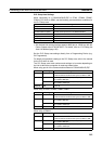
The DM Area words that are allocated and the contents of the settings are
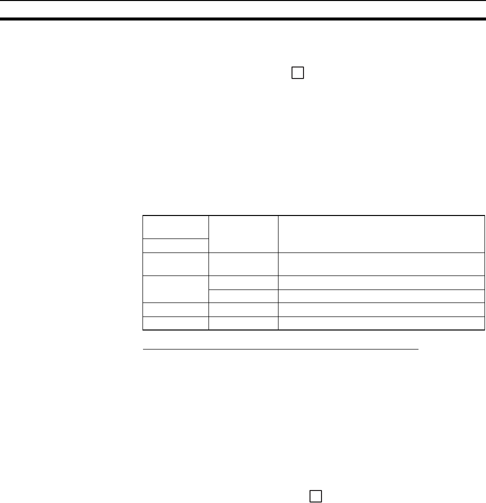
given in the following table.
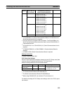
Allocated DM
Area words
Setting Setting Contents
Port 2
DM32010 8000 Host link mode, 2 stop bits,
data length 7 bits, even parity,
DM32011 0000 Communications speed: 9600 bps
0007 Communications speed:19200 bps
DM32012 0000 Transmit delay time0 ms.
DM32013 0000 No CTS control Unit, No.0 for host link
4
4