


108
Connecting to the Host’s RS-422A/485 Port Section 5-2
Setting the DIP Switches on a C200HX/HG/HE(-Z)E Communications
Board
Set the switches on a C200HX/HG/HE(-Z)E Communications Board as fol-
lows.
Switch 1: (4-wire = RS-422A)
Switch 2: ON (terminator ON = terminating resistance enabled).
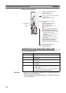
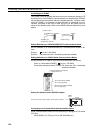
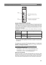
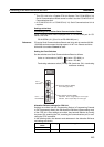
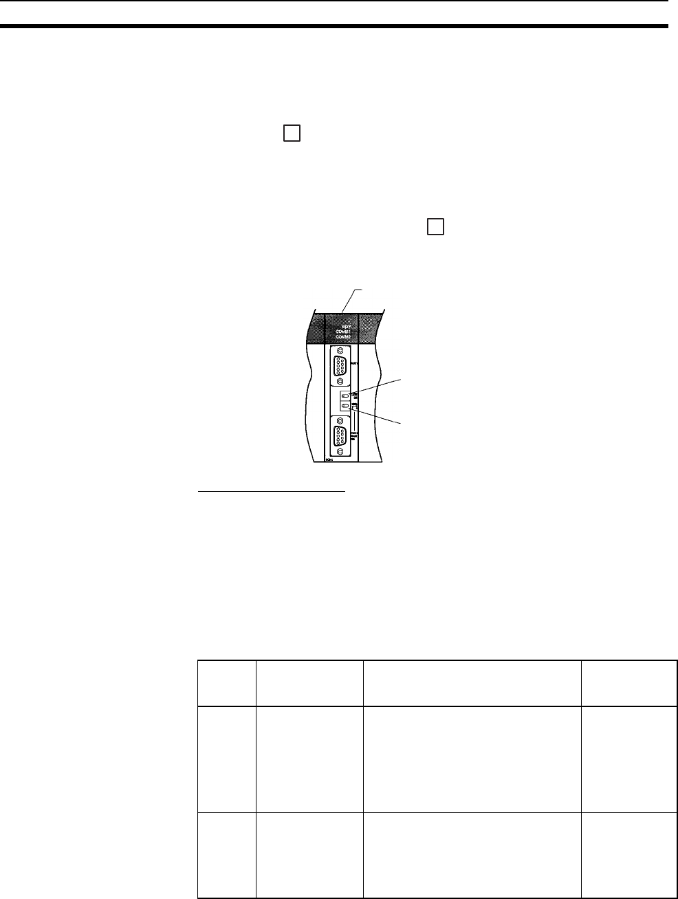
Setting Switches on a CQM1H Serial Communications Board
Set the switches on a CQM1H Serial Communications Board as follows.
2-wire or 4-wire selector (WIRE): (4-wire = RS-422A)
Terminating resistance switch (TERM): ON (terminator ON = terminating
resistance enabled).
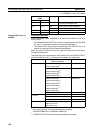
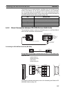
Using the NT Link (1:N)
Method
Compatible Host Units
The OMRON PLCs that can be connected using the RS-422A/485 NT Link
(1:N) method are the CS/CJ-series, C200HX/HG/HE(-Z)E, and CQM1H mod-
els only. A Serial Communications Board/Unit or a Communications Board
must be installed to make the connection.
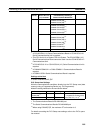
Check the model and series of the PLC against the type of CPU Unit or com-
munications board before making the connections.
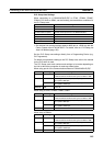
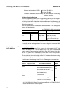
The hosts that can be connected to the RS-232C port of the NT631/NT631C
by the RS-422A NT Link (1:N) function via an Adapter are indicated in the
table below.
4
4
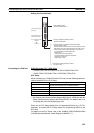
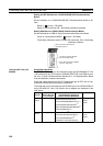
Serial Communications Board
(Inner Board slot 1)
Terminator Switch (TERM)
Set to ON (right side).
Wire Selection Switch (WIRE)
Set to 4 (right side).
PLC
Series
CPU Units with
Built-in NT Link
(1:1) Function
CPU Unit that becomes
connectable by installing a
Communications Board/Unit
Model Name
CS
Series
CS1G-CPU42/43/44/45-E(V1)
(*1)
CS1H-CPU63/64/65/66/67-E(V1)
(*1)
CS1G-CPU42H/43H/44H/45H
(*1)
CS1H-CPU63H/64H/65H/66H/67H
(*1)
CS1D-CPU65H/67H
(*2)
CS1G
CS1H
CS1D
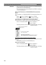
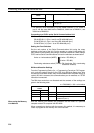
CJ
Series
CJ1G-CPU44/45
(*3)
CJ1G-CPU42H/43H/44H/45H
(*3)
CJ1H-CPU65H/66H/67H
(*3)
CJ1M-CPU11/12/13/21/22/23
(*3)
CJ1G
CJ1H
CJ1M