


PRINTER NOTE: Page size 9” x 9.25”. Align this page to top, right hand corner. Back box bleeds off
top and right edge. Left side of page extends to 9.25 inches.
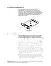
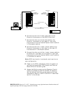
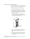
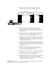
9 Connect one end of a 1 meter jumper cable to the
Channel 0 connector on the lower or left side I/O
Interface card in the master cabinet.
10 Connect the other end of the 1 meter jumper cable to
the Channel 0 connector on the lower or left side
two-channel Ultra Extender card installed in the
slave #1 cabinet.
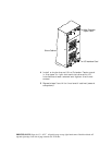
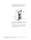
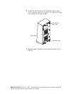
11 Connect one end of a second 3 meter data cable to
the Channel #2 connector on the RAID Controller (or
the Channel #1 connector of a second single channel
RAID Controller).
12 Connect the other end of the data cable to the
Channel 1 connector on the upper or right side two-
channel Ultra Extender card.
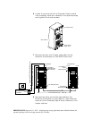
13 Connect one end of a second 1 meter jumper cable to
the Channel 1 connector on the lower or left side I/O
Interface card in the master cabinet.
14 Connect the other end of the second 1 meter jumper
cable to the Channel 1 connector on the lower or left
side two-channel Ultra Extender Option card
installed in the slave cabinet.
Note: SCSI termination is automatic and requires no
user configuration
15 Power on the DEU subsystems. After the power-on
self-test has completed, HDD Status and Channel
Mode LEDs will be solid green.
16 Access the Options menu on the Operator Control
Panel and choose the SAFTE CHAIN ID selection.
Set the cabinet identities of the master and slave
subsystems. Refer to “SAFTE CHAIN ID” described
earlier in this Guide.
17 After setting the cabinet identifications you must
power cycle the subsystems. Observe normal power
cycling precautions by waiting a minimum of five
seconds before adding power again.
This will reset the SCSI IDs to a default setting that
prevents a SCSI ID conflict under normal conditions,
refer to “Default Configurations” later in this
section.
18 Power up your computer system and run the
configuration program.