PRINTER NOTE: Page size 9” x 9.25”. Align this page to top, right hand corner. Back box bleeds off
top and right edge. Left side of page extends to 9.25 inches.
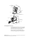
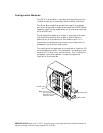
The drive mounting design incorporates a rail system
with built-in connectors making it possible to “hot
swap” a drive without shutting down the system. This
design allows for easy installation with minimal force
and latching clips to secure the drives into place.
Note: All drives in an array should be of the same
capacity. If the drives are mixed, all of the drives in
the array are assigned the capacity of the smallest size
drive.
Power Switch
The power switch is located inside the locking front
door and controls AC power to all of the power supplies.
This positioning of the switch deters unauthorized
users from powering down the DEU provided the door
is locked. The switch is recessed to prevent inadvertent
activation during service activity.
The switch is labeled with a “I” for the ON condition
and “O” for the OFF condition and is illuminated when
the power is on for easy identification. Depending on
the orientation of the subsystem (i.e., in the rack
configuration) the “I” label will appear as a — and
should be interpreted as the ON condition.
Fault LEDs
Drive Fault LEDs are provided inside the front door to
aide in identifying the failed (or problem) disk drive.
These LEDs are aligned with their respective
drive/drive bay. An illuminated LED (amber) indicates
the failed or problem drive.
SAF-TE Card
The SAF-TE card contains the control and monitoring
electronics for the subsystem cabinet. It provides the
central data link between the enclosure and the host
system.


