


PRINTER NOTE: Page size 9” x 9.25”. Align this page to top, right hand corner. Back box bleeds off
top and right edge. Left side of page extends to 9.25 inches.
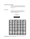
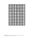
Jumpers
Caution: Jumper configuration to be performed by
qualified service personnel only.
Disconnect the AC power cord prior to accessing any
component inside the rear cabinet.
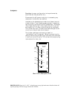
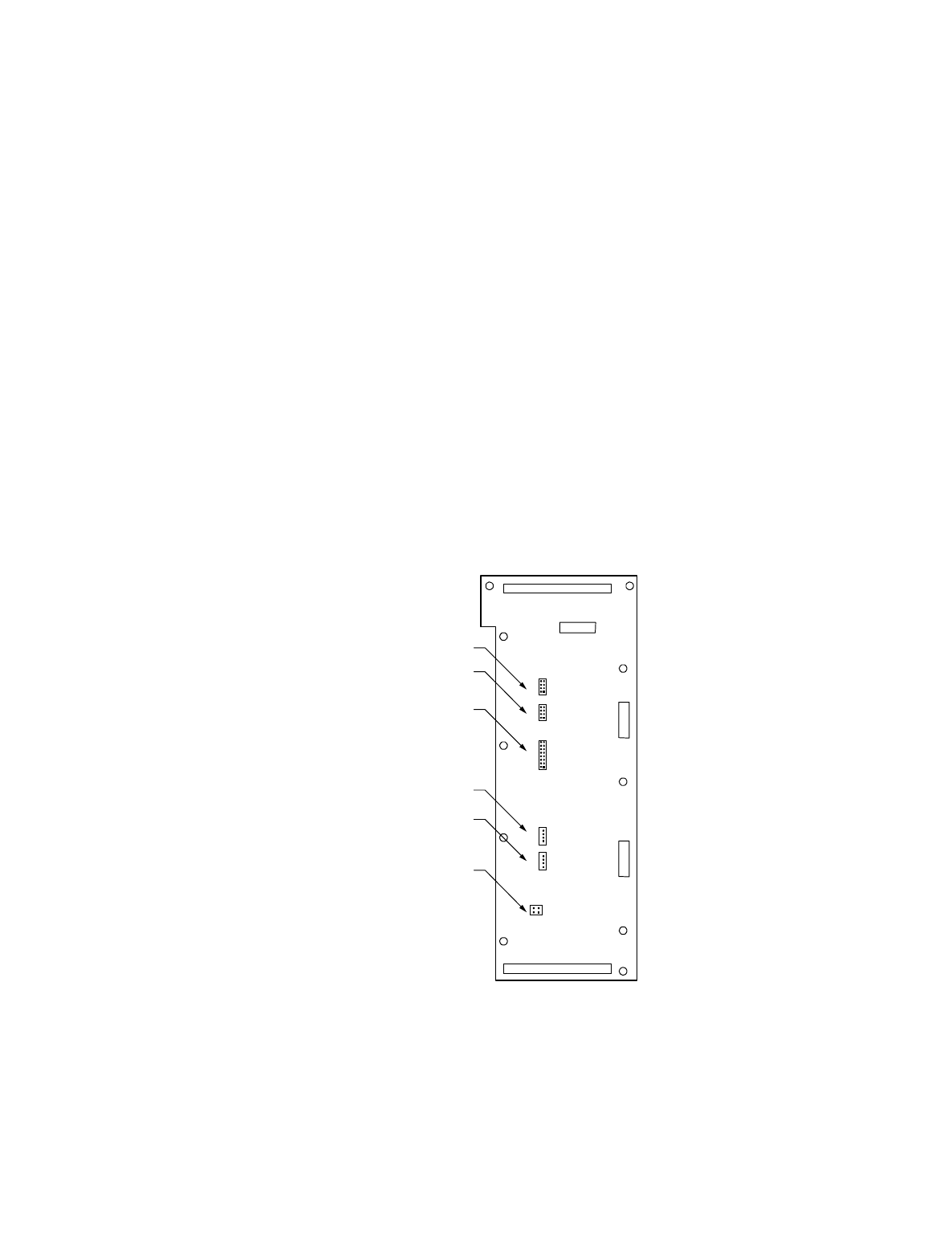
Located on the backplane printed circuit board are six
jumper blocks. From these jumpers system integrators
can manually configure the DEU subsystem. To change
the jumper setting, pull the jumper plug off its pin(s)
and carefully fit in down onto the pin(s) as indicated.
This allows the user to make reversible changes to the
circuitry on the printed circuit board.
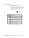
The jumper settings are known as “open” or
“unjumpered” and “jumpered.” When unjumpering the
setting remove the jumper plug from both pins and seat
it over just one of the pins. This allows the jumper plug
to be stored for later use.
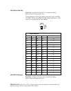
JP3
JP3
JP2
JP2
JP4
JP4
J15
J15
J17
J17
JP5
JP5
1
S2S
SCSI
IDs
S2S
CONFIG
SCSI
IDs
FAN
OEM FAN
REMOTE
DELAY
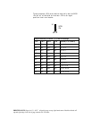
8
1
1
1
12
1
8
4
4
43
16
Rear View of Backplane PCB