


16 C2928M-A (4/07)
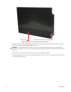
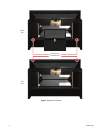
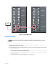
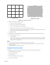
For stand-alone units, connect the video input to the Analog 1, Analog 2, or Digital In input. Multiple inputs can be connected simultaneously.
Refer to Figure 6.
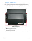
For wall systems, connect the video input to the Analog 1, Analog 2, or Digital In input. Multiple inputs can be connected simultaneously.
Loop the video out from the first display to the input connector of the second display. Continue looping until all displays are connected.
If you used an analog input on the first display, you can loop the video to the other displays using the anlog inputs and outputs. However, the
Digital Out connector carries video from the analog inputs as well as the digital input. For improved image quality it is recommended that analog
video from the first display be looped using the digital connectors.
All of the video inputs have buffered loop-through output connectors.
Analog 1 and Analog 2 are 15-pin VGA-type connectors. The PMCD750 will accept a wide range of computer inputs with resolutions up to
1600 x 1200 and 1920 x 1080. Each of these connectors has a dedicated loop-through output. These connectors are also used for RGB video with
separate horizontal and vertical sync, composite sync, or sync on green; also for YPbPr video at 480p, 720p, or 1080i.
When an analog input has a source with sync on green or composite sync, the DVI Out may not show the picture properly. If the source is present
at power up, it typically works well, but if the source is disconnected and then reconnected, the DVI loop-through stops working for these two
types of sync.
Digital In is a standard DVI cable input. It has a loop-through, but the Digital Out connector is not dedicated exclusively to the Digital In connector.
Instead, the Digital Out connector carries the picture of the currently selected input. For instance, if the Analog 1 connector is selected, the pic-
ture on the Digital Out connector is a DVI version of that Analog 1 picture.
LOOP-THROUGH LIMITS
A signal cannot loop-through indefinitely due to degredation of the signal as it progresses through the loop. Depending on the strength of the
signal, the loop-through limit is four units for digital (DVI) signals, and twelve units for analog (VGA) signals. When a loss of signal is experienced
due to loop-through degredation, a distribution amplifier can be used to compensate.
CONNECTING RS-232 AND RS-485 CONTROL
With serial control, you can control a stand-alone unit, a whole wall, several walls, and any single display in a wall.
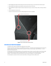
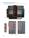
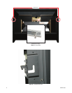
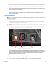
To connect an external controller, refer to Figure 7 and do the following:
1. Using a straight-through computer serial cable, connect the RS-232 input of the stand-alone unit or the first unit in the wall to the serial out
port of the external control device, such as a video controller.
2. Connect this first display’s RS-485 Out to the next display’s RS-485 In.
NOTES:
•
For best results, the RS-485 cables should be twisted pair. The pairs are pins 3 and 6 (signal) and pins 1 and 2 (ground). Cat5 cable has the correct
twisted pairs.
• For very long runs of RS-485 cable, it may be necessary to terminate the last PMCD750 unit in the loop. To terminate the last unit, refer to the
Controlling with RS-232/RS-485 Interface section.