


C2928M-A (4/07) 19
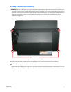
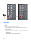
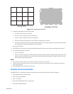
3. Install the screens to the left and right of the center screen to complete the bottom row. After adding a screen, press it toward the center.
4. Check the line of this bottom row of screens. If they are not straight, use shims on the top of the screen support until the screens are
straight.
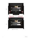
5. Starting in the second row and working up, install all remaining center screens. Lift each screen and press it in so that it does not scrape on
the screen below. Continue until you reach the top.
6. Working upward and outward, finish all the rows.
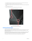
7. Perform a final check of screens for alignment with each other. The horizontal and vertical spaces between each screen should form
straight lines where they intersect.
CONNECTING POWER
NOTE: The use of an uninterruptible power supply (UPS) manufactured by Powerware, Model PW9120 700i, or equivalent, is required to comply
with EMC Directive 89/336/EEC.
To apply power to the display:
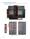
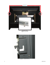
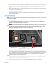
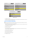
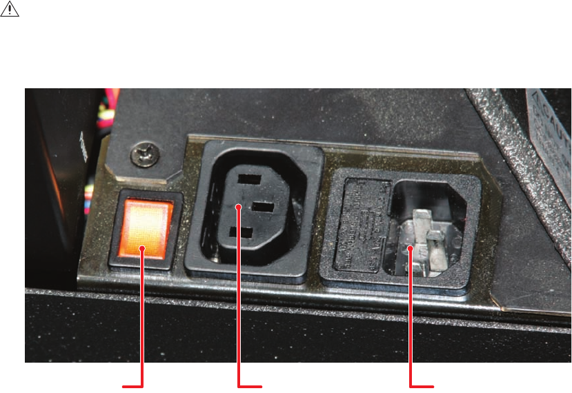
1. Bring in AC power next to the electronics module. Connect the power to the receptacle located on the rear panel. The voltage can be
115 VAC (90–132 VAC) or 230 VAC (200–254 VAC). Refer to Figure 10.
2. The AC power can be looped through to the next PMCD750 unit, resulting in fewer main outlet sockets needed for operation. The total
number of units in one power loop cannot exceed four (115 VAC) or eight (230 VAC) units.
Figure 10. Power Switch and Receptacles
3. Turn on the power switch for each display. When AC power is applied, there are a few seconds of apparent inactivity in which the
electronics module begins start up and initialization. Next, if the optical engine is warm, the intake and lamp fans start. Because the service
life of the lamp can be significantly shortened if turned on when hot, the lamp cannot be turned on during this time. The lamp fan runs for
approximately one minute to ensure the lamp is cool. If the temperature sensor on the optical engine determines that the lamp is
sufficiently cool at power up, this cool-down period is skipped.
NOTES:
•
The AC switch on each PMCD750 unit controls that display only. Turning off the switch on any display does not cut the AC power to the other
displays. The switch is lit when it is ON and there is AC power to the PMCD750 unit.
• The AC input is fused with a 10 A fuse. If the fuse in any PMCD750 unit blows, all displays downstream from this one will go off.
WARNING: Do not exceed the recommended number of PMCD750 units linked in series for AC power or the current draw will be too great.
POWER SWITCH AC INAC OUT