


MGC+ Hardware and Installation Manual
4-27
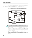
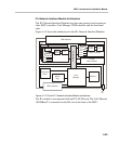
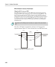
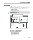
Each 160-pin connector can be connected to one 160-pin connector located
on the front panel of the MPI box.
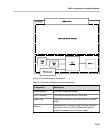
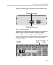
Figure 4-15: MPI box front panel
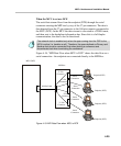
Each of the 160-pin connectors on the MPI box interfaces to four serial ports
found on the back of the MPI box. Therefore, each MPI-4/8 Network
Interface module can be connected to up to eight ports. Each port has two
connectors: 37-pin connector and the 25-pin connector. The 25-pin connector
is used to dial to an endpoint over an ISDN switch. (In leased line connection
this port is not used.) The 37-pin connector connects to the serial cable
coming from the DCE.
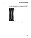
Figure 4-16: MPI box rear panel
PORTS
1-4
A A
B
B
PORTS
5-8
PORTS
9-12
PORTS
13-16
160-pin connector
Converts data from four ports
160-pin connector
Converts data from four ports
P1
P2
P3
P4
P5
P6
P7
P8
P9
P10
P12
P13
P11
P14
P15
P16
DIAL DIAL
DIAL
DIAL DIAL
DIAL
DIAL DIAL
DIAL
DIAL
DIAL DIAL
DIAL
DIAL
DIAL
DIAL
P12
P13
P14
P15
P16
P7
P8
P9
P10
P11
P1
P2
P3
P4
P5
P6
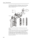
Single port
connection
RS-449 37 pin
D-type
connector
RS-336 25 pin
D-type
connector