


MGC+ Hardware and Installation Manual
3-3
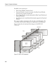
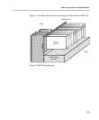
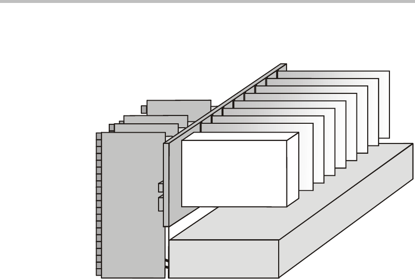
Figure 3-3 describes the functional block diagram of the complete MGC+50.
Figure 3-3: MGC+50 components
MUSIC I/O
H.323 I/O
NET I/O
Rear
Backplane
Front
Power Supply
Module
NE
T
-
8
I
P
+
A
u
d
i
o
+
A
u
d
i
o
+
M
u
x
+
V
i
d
e
o
+
V
i
d
e
o
+
V
i
d
e
o
+
CU I/O
Control
Module