


MGC+ Hardware and Installation Manual
4-5
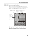
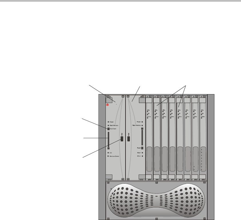
MGC+50 Components Location
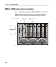
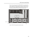
Figure 4-4 shows the front panel of the MGC+50. The front panel provides
access to the Main Control Module, the Functional Modules, and the Power
Supply Module. Status LEDs on the Main Control Module, Functional
Modules, and Power Supply Module indicate the status of the system.
Figure 4-4: MGC+50 front panel
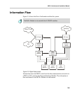
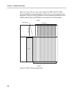
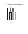
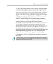
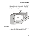
Figure 4-6 shows the top view of the inside of the MGC+50. The Main
Control Module, Functional Modules, and I/O cards are all connected to the
Backplane. The Power Supply Module is located underneath the Main
Power
Out
P
O
L
Y
C
O
M
R
M
G
C
+
Line 1
Line 2
Line 3
Line 1
Line 4
Line 2
Line 5
Line 6
Line 7
Line 8
ReadiConvene IAM
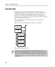
MGC+ Control
Unit (CU)
MGC+ Functional
Modules
Compact Flash
slot
Shut Down
button
Universal
Serial Bus port