


MGC+ Hardware and Installation Manual
3-7
MGC+ Manager Interface
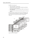
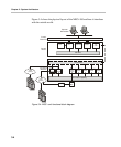
As shown in Figure 3-4, “MGC+ unit functional block diagram” on page 3-4,
the Main Control Unit communicates with the MGC+ Manager through the
LAN interface or the RS-232 interface.
Power Supply Flow
For the MGC+100, the AC power inlet is connected by a switch through a 15
Amp. circuit breaker and then filtered to the power plan and then to the AC
power supply module. 12V is also delivered to the fans.
For the MGC+50, the AC power inlet is connected through a 15 Amp. circuit
breaker and then filtered to the AC power supply module. 12V is also
delivered to the fans.