


Chapter 4 - Hardware Description
4-2
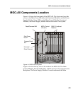
MGC+100 Components Location
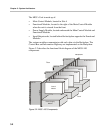
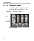
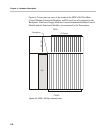
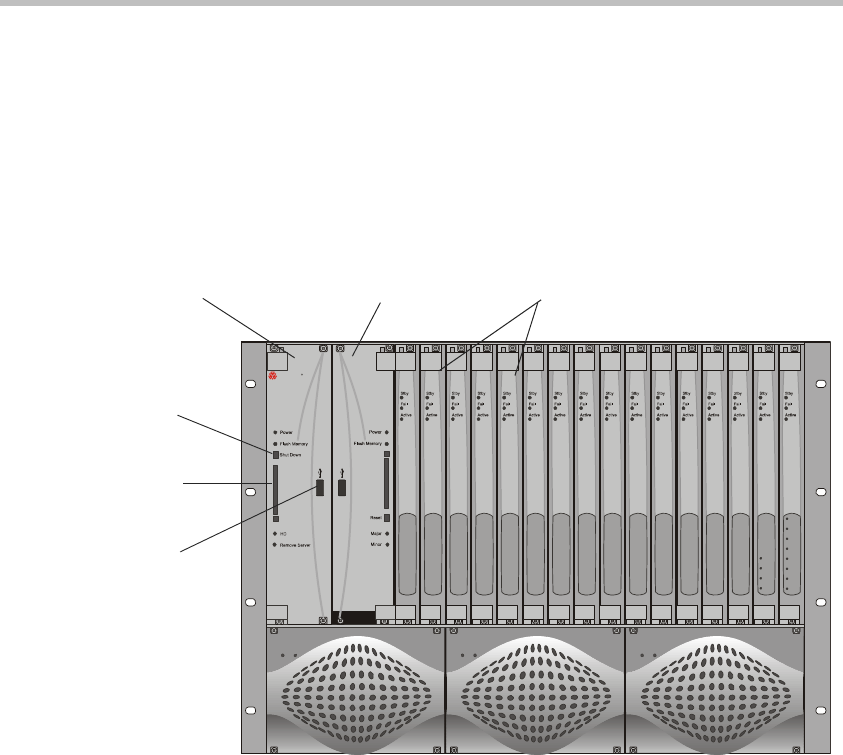
Figure 4-1 shows the front panel of the MGC+100. The front panel provides
access to the Main Control Module, the Functional Modules, and the Power
Supply Modules. Status LEDs on the Main Control Module, Functional
Modules, and Power Supply Modules indicate the status of the system.
Figure 4-1: MGC+100 front panel
Power
OutIn
Power
OutIn
Power
OutIn
P
O
L
Y
C
O
M
R
M
GC+
Line 1
Line 1
Line 2
Line 2
Line 3
Line 3
Line 4
Line 4
Line 5
Line 6
Line 7
Line 8
ReadiConvene IAM
MGC+ Control
Unit (CU)
MGC+ Functional
Modules
Compact Flash
slot
Shut Down
button
Universal
Serial Bus port