


Chapter 3 - System Architecture
3-4
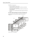
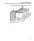
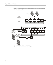
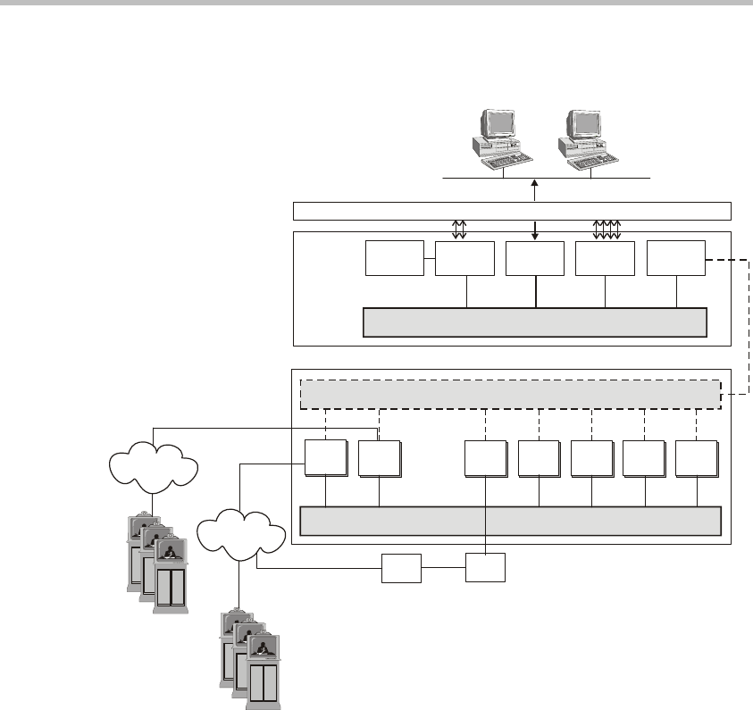
Figure 3-4 shows the physical layout of the MGC+100 and how it interfaces
with the outside world.
Figure 3-4: MGC+ unit functional block diagram
Hard
Disk
RS232
RS232
Main
CPU
Ethernet
External
Compact Flash
Serial
Inteface
CComm
and
C8M
CPU Bus
Control Bus
Information Highway
Control
Board I/O
Control
Board
Operator
Workstation
Functional
Modules
H323
Network
ISDN
Network
Audio
Module
Video
Module
Data
Module
MUX
Module
MPI
Network
Interface
IP
Network
Interface
ISDN
Network
Interface
MPI
Box
DCE
+
++