


MGC+ Hardware and Installation Manual
2-29
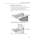
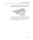
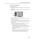
6. Once the, Server panel, Main Control Module, the power supply module
and the boards are removed, unscrew the side screws from inside the
MGC+50, and then remove the plate from both MGC+50 sides.
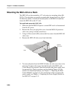
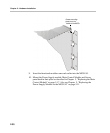
7. To remove the plate from the right side of the MGC+ unit remove the
appropriate number of functional modules to allow access to the screws.
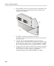
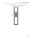
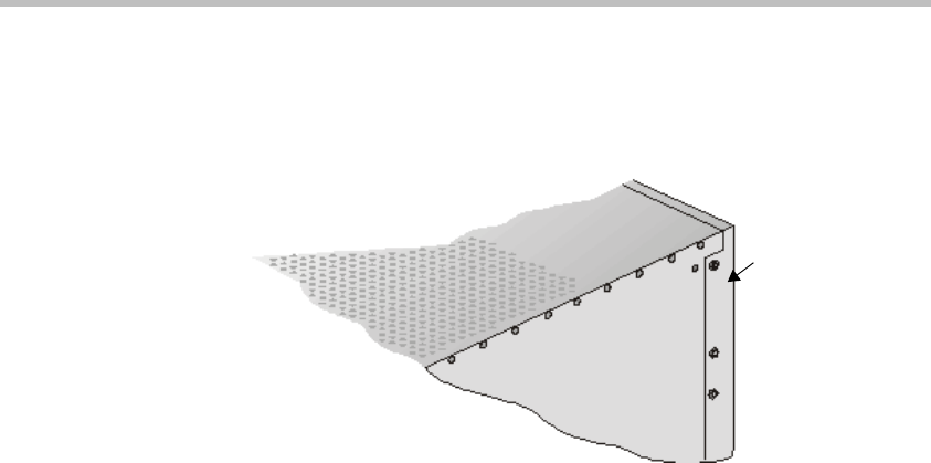
8. From the inside of the MGC+50, screw the mounting bracket to the side
of the MGC+50, securing the screws in the mounted nuts.
front
Remove
plate