Rev.2.00 Nov 28, 2005 page 164 of 378
REJ09B0124-0200
M16C/6N Group (M16C/6NK, M16C/6NM) 15. Serial Interface
Under development
This document is under development and its contents are subject to change.
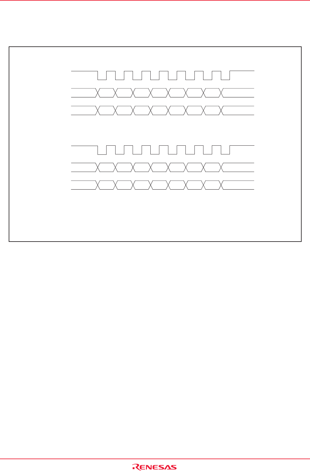
15.1.1.3 LSB First/MSB First Select Function
Use the UFORM bit in the UiC0 register (i = 0 to 2) to select the transfer format.
Figure 15.13 shows the transfer format.
Figure 15.13 Transfer Format
15.1.1.4 Continuous Receive Mode
In continuous receive mode, receive operation becomes enable when the receive buffer register is read.
It is not necessary to write dummy data into the transmit buffer register to enable receive operation in
this mode. However, a dummy read of the receive buffer register is required when starting the operation
mode.
When the UiRRM bit (i = 0 to 2) = 1 (continuous receive mode), the TI bit in the UiC1 register is set to “0”
(data present in UiTB register) by reading the UiRB register. In this case, i.e., UiRRM bit = 1, do not write
dummy data to the UiTB register in a program. The U0RRM and U1RRM bits are bit 2 and bit 3 in the
UCON register, respectively, and the U2RRM bit is bit 5 in the U2C1 register.
(1) When the UFORM bit in the UiC0 register = 0 (LSB first)
D0
D0
D1 D2 D3 D4 D5 D6 D7
D1 D2 D3 D4 D5 D6 D7
TXDi
RXDi
CLKi
(2) When the UFORM bit in the UiC0 register = 1 (MSB first)
D6 D5 D4 D3 D2 D1 D0
D7
D7
D6 D5 D4 D3 D2 D1 D0
TXDi
RXDi
CLKi
* This applies to the case where the CKPOL bit in the UiC0 register = 0
(transmit data output at the falling edge and the receive data taken in at
the rising edge of the transfer clock) and the UiLCH bit in the UiC1
register = 0 (no reverse).
i = 0 to 2


