Rev.2.00 Nov 28, 2005 page 45 of 378
REJ09B0124-0200
M16C/6N Group (M16C/6NK, M16C/6NM) 7. Bus
Under development
This document is under development and its contents are subject to change.
During memory expansion or microprocessor mode, some pins serve as the bus control pins to perform data
_______ _______
input/output to and from external devices. These bus control pins include A0 to A19, D0 to D15, CS0 to CS3,
_____ ________ ______ ________ ________ ________ __________ _________
RD, WRL/WR, WRH/BHE, ALE, RDY, HOLD, HLDA and BCLK.
7.1 Bus Mode
The bus mode, either multiplexed or separate, can be selected using the PM05 to PM04 bits in the PM0
register.
7.1.1 Separate Bus
In this bus mode, data and address are separate.
7.1.2 Multiplexed Bus
In this bus mode, data and address are multiplexed.
7.1.2.1 When the input level on BYTE pin is high (8-bit data bus)
D0 to D7 and A0 to A7 are multiplexed.
7.1.2.2 When the input level on BYTE pin is low (16-bit data bus)
D0 to D7 and A1 to A8 are multiplexed. D8 to D15 are not multiplexed. Do not use D8 to D15.
External devices connecting to a multiplexed bus are allocated to only the even addresses of the
microcomputer. Odd addresses cannot be accessed.
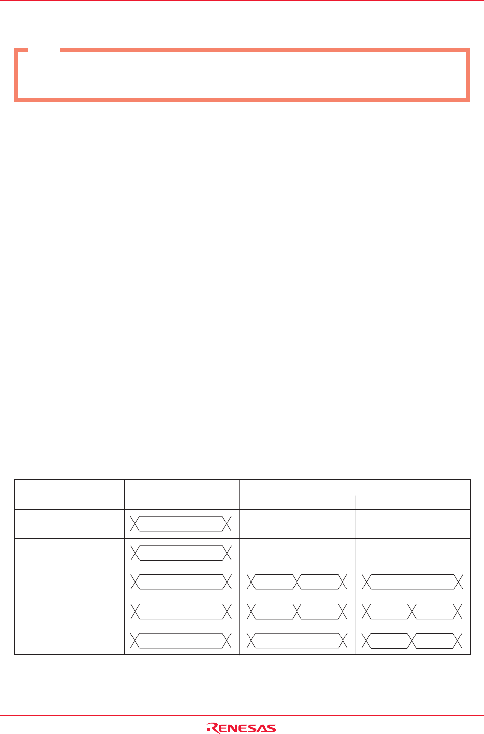
Table 7.1 shows the difference between a separate bus and multiplexed bus.
Table 7.1 Difference between Separate Bus and Multiplexed Bus
Pin Name
(1)
Separate Bus
Multiplexed Bus
BYTE = H BYTE = L
P0_0 to P0_7/D0 to D7 D0 to D7 (NOTE 2) (NOTE 2)
P1_0 to P1_7/D8 to D15 D8 to D15
I/O Port
(NOTE 2)
P1_0 to P1_7
P2_0/A0(/D0/-) A0 A0 D0 A0
P2_1 to P2_7/A1 to A7
A1 to A7 A1 to A7 D1 to D7 A1 to A7 D0 to D6
(/D1 to D7/D0 to D6)
P3_0/A8(/-/D7) A8 A8 A8 D7
NOTES :
1. See Table 7.6 Pin Functions for Each Processor Mode for bus control signals other than the above.
2. It changes with a setup of PM05 to PM04, and area to access. See Table 7.6 Pin Functions for Each
Processor Mode for details.
7. Bus
Note
7. Bus explains as an example of a Normal-ver..
Not available the bus control pins in T/V-ver..


